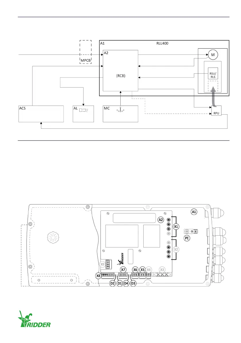
5.3 Overview and funcon diagram
The diagram that follows shows the RLL400 control-unit in a system. Ridder Drive Systems connects
the components (if applicable) in the framework A1.
5.4 Wiring diagram: Control board (RCB)
The diagrams that follow show:
• The RLL400 housing (A1) and the RCB control-board (A2)
• The standard connecons and oponal connecons with related connectors
• The related secons with the wiring diagrams and informaon.
Ridder connected X2, X3, X4, X7* and X9 (if applicable).
* X7 is parally connected. Refer to §5.10 and complete the connecons.
RLL400 housing:
Automac Control Alarm Manual Control
Control Board
Supply Voltage
Temperature
Limit Switch
Power supply 24 V DC
Supply Voltage
24 V AC/DC Control
Fault Contact
OPTIONAL OPTIONAL
Reference Monitoring
Posion Feedback
OPTIONAL
Ridder Drive Systems B.V.
T +31 (0)341 416 854 - F +31 (0)341 416 611 - I ridder.com
15
 Loading...