6. USER INSTRUCTIONS
6.1 Usage - Condions and starng points
The condions and starng points that follow are applicable when you use the RLL400 control-unit.
Automac Control
Temperature
Waing me
6.2 Status LEDs
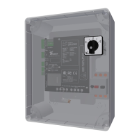
The four LEDs D1 (green), D2 (red), D3 (red) and D4 (red) on the control board (A2) give status
indicaon of the system. This informaon is important for troubleshoong.
Refer to §9.1 and §9.2. These secons tell about malfuncons and blink codes that can occur.
If a manual control (MC) (277950) is connected, the two LEDs (green and red) agree with the LEDs
D1 and D2 on the control board (A2). The control board (A2) and the manual control (MC) show the
blink codes (D1 and D2) at the same me.
The motor can start and stop automacally without a warning.
Persons can be in danger of life if they touch a system that is in
operaon.
The motor can start and stop automacally without a warning but
will stay energized. De-energize the system during work on the drive
unit or the system. Persons can be in danger of life if they touch a
system that is in operaon.
A drive unit can get high temperatures. If necessary take protecve
precauons to prevent injuries.
The waing me must be approximately 2 seconds when you change
the direcon-of-rotaon. The electric motor must stop.
This prevents that it connues in the inial direcon.
Ridder Drive Systems B.V.
T +31 (0)341 416 854 - F +31 (0)341 416 611 - I ridder.com
21
 Loading...