2.3 Residual risks
Automac controls
The Ridder drive-units are usually used in automac controlled systems. Persons who do work or
stay near the system must know about that. If persons or their clothes touch the system during
operaon, it can be dangerous.
Forces
Because of the forces in the systems (in which the drive unit is installed), Ridder cannot be sure that
there will be no injury to persons or damage to the system.
2.4 Symbols and abbreviaons
This secon tells about used symbols and abbreviaons in this manual. The table that follows gives
the descripons.
Symbol Description Symbol Description
1L1 Power IN (A2) MC Manual Control (external)
3L2 Power IN (A2) MPCB Motor-Protecon Circuit-Breaker
5L3 Power IN (A2) N Neutral wire
2T1 Power OUT (EM) PE Protecve earth
4T2 Power OUT (EM) PTC PTC thermistor
6T3 Power OUT (EM) RCB Ridder control-board
ACS Automac control-system RLL Ridder LogicLink
AL Alarm (circuit) RLS Limit-switch system
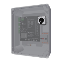
A1 RLL400 housing RPU Digital posioning-meter
A2 Control board RSU Limit-switch system
D1 Status LED - Green RW Motor gearbox
D2 Status LED - Red X1 Power input (RCB)
D3 Status LED - Red X2 Power output (EM)
D4 Status LED - Red X3 Transformer
EM, M Electric motor, Motor X4 PTC input
ES11,ES12 Duty switch RSU/RLS X5 Fault-contact output
ES21,ES22 Safety switch RSU/RLS X6 Automac-control input
GND Return wire of control signal (ACS) X7 RPU reference-input
I Current in Amperes (A) X8 Manual-control input
L1, L2, L3 Voltage source X9 Limit-switch input
Persons can be in danger of life if they touch a system that is in
operaon.
Ridder Drive Systems B.V.
T +31 (0)341 416 854 - F +31 (0)341 416 611 - I ridder.com
6
 Loading...