6.4 Alarm
The RLL400 control-units have a fault contact for feedback. The maximum current for the fault
contact is 0.5 A at 24 V AC/DC.
The fault contact is in operaon:
• When the electric motor is thermally stopped
• When phase failure occurs
• When the safety switch is operated
• When there is no power supply.
6.5 Safety funcons and stop funcons
The RLL400 control-unit has the safety funcons and stop funcons that follow:
1. Phase detecon to protect from a change of phases in the power supply. This makes sure that
the direcon-of-rotaon of the motor gearbox is correct.
2. Delay me when the direcon-of-rotaon is suddenly changed. This prevents that it connues in
the inial direcon.
3. Stops automacally when the safety switch is operated. Manual or automac control in the
opposite direcon-of-rotaon stays possible.
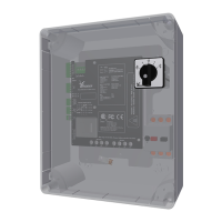
4. Error-message indicaon with four LEDs on the control board (A2).
5. Feedback of error messages with a fault contact.
Connect the fault contact to an alarm unit or an alarm input of a
control system.
Ridder Drive Systems B.V.
T +31 (0)341 416 854 - F +31 (0)341 416 611 - I ridder.com
23
 Loading...