RIGOL
© 2008 RIGOL Technologies, Inc.
User’s Guide for DS1000B series
To Understand the Vertical System
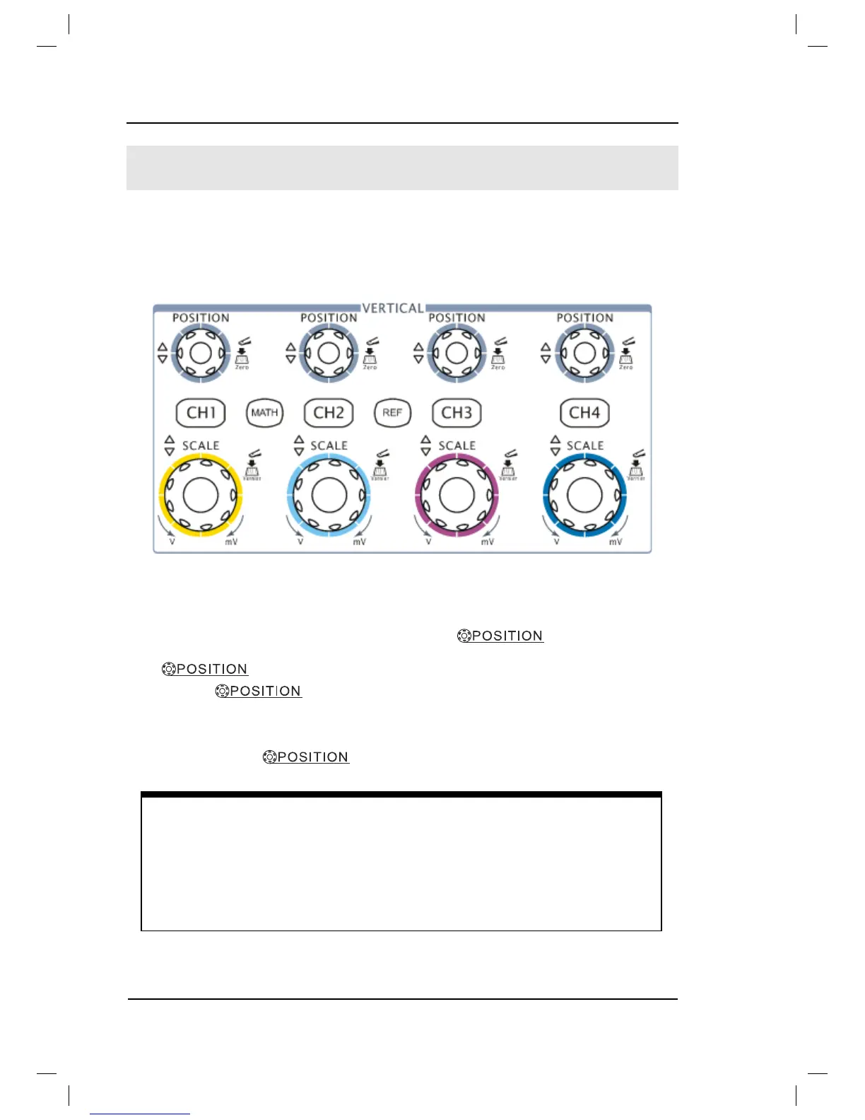
As shown in Figure 1-9, there are several series buttons and knobs in the VERTICAL
control area. The following exercises will gradually conduct you to be familiar with
the using of the vertical parameters settings.
Figure 1-9
The vertical control window
1. Center the signal on the display with the
knob.
The
knob moves the signal vertically, and it is calibrated. Note that
turning the
knob, a voltage value is displayed for a short time
indicating its value with respect to the ground reference located at the center of the
screen. Also notice that the ground symbol on the left side of the display moves in
conjunction with the
knob.
Measurement hints
If the channel is DC coupled, measuring the DC and AC components of the
signal by simply noting its distance from the ground symbol.
If the channel is AC coupled, the DC component of the signal is blocked, allow
you to use greater sensitivity to display the AC component of the signal.