2.
Deragliatore
fill
• Controllare la
quota
"c"
(fig. 21) e qualora
non
corrispondesse a quella riportata
sulla tabella di fasatura, aiientare la vite P e registrare in modo da
ottenere
la
quota
prescritta.
•
Bloccare
la
vite
P.
- Posizionare I'astina porta deragliatore B a mm 6,8— 7 (fig. 27). Per ottenere tale
quota,
altentare
le viti A ed eseguire lo
spostamento
necessario
dell'astina
B.
-
Bloccare
le
viti
A.
Con barra ago al punto morto Inferiore, montare suM'astina ideragiiatori C (fig.
27) controllando che ialoro estremita siacirca 0,8 —0,9 mmdall'ago e che nella
fase di movimento sfiorino la placca d'ago e la griffa senza toccarle (fig. 28).
- I deragiiatori eseguono solo uno spostamento laterale. Per anticipare o ritardare
questo
movimento, bisogna aiientare i
due
grani interni Q dell'eccentrico 0 delta
biella (fig. 21) e, tenendo
ferrrvD
I'eccentrico 0, ruotare il volantino della
macchina
sino
ad
ottenere
la
condizione
illustrata
in
fig.
27.
2.Thread
deflector
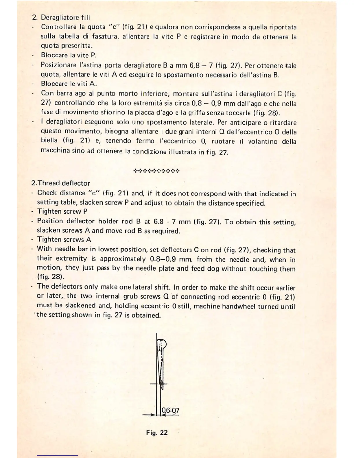
- Check distance
"c"
(fig. 21) and, If It does not correspond with that indicated in
setting table, slacken screw P and adjust to obtain the distance specified.
-
Tighten
screw
P
- Position deflector holder rod 8 at 6.8 - 7 mm
(fig.
27). To obtain this setting,
slacken screws A and move rod B as required.
-
Tighten
screws
A
-
With
needle
bar in
lowest
position, set deflectors Con rod
(fig.
27),
checking
that
their extremity is approximately
0.8-0.9
mm. from the needle and, when in
motion, they just
pass
by the
needle
plate and feed dog without touching them
(fig.
28).
- The deflectors only make one lateral shift. In order to make the shift occur earlier
or later, the two internal grub
screws
Q of connecting rod eccentric 0
(fig.
21)
must be slackened and, holding eccentric 0 still, machine handwheel turned until
the
setting
shown
in fig.
27
is
obtained
0.6f07
Fig.
22