Linear installation guide 13563-B 02-19 | 39
down-and-out ueing
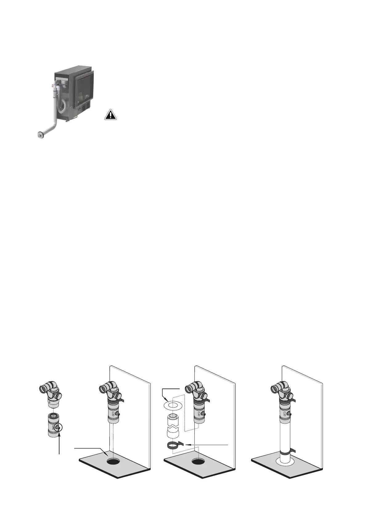
Flueing options
The down and out ue allows for the adaption ue component to face
downwards, and for the ue to run vertically through a hole in the oor, and
then terminate horizontally outside—ue must terminate 300 mm above the
ground.
I
n
t
e
r
i
o
r
wa
l
l
I
n
te
ri
o
r
wa
l
l
Wall plate
Stand off clip
I
n
t
e
r
i
o
r
w
a
l
l
Floor penetration
Ø 80 mm
Cap off the drain
tube with a small
cable tie
Overview of installation steps
1. Lubricate all inner pipe o-rings with the silicone grease provided.
2. Join the ue transition and condensate together ensuring the condensate arrow points
downwards. Even though the condensate is not actually connected in this ue arrangement,
the condensate component serves as a transition piece between the transition casting and the
ue pipe. The transition component must not be connected directly to the ue pipe due to the
heat of the ue gases. Cap off the condensate drain tube with the cable tie supplied.
3. Fit lengths of ue pipe as required.
4. The ue penetration should have made at the same time as the cutout for the gas connection.
Floor penetration should be a 80 mm diameter hole—ensure edges are smooth.
5. Pass the ue pipe through the wall plate and through the oor penetration, and secure the wall
plate in place to seal the oor.
6. Prepare the horizontal section of the ue system under the oor by connecting the ue pipe
and bends as required. Allow for a 2° continuous fall from the rst section of the horizontal ue
pipe to the wall penetration.
7. Create the wall terminal, refer p. 41, ensuring a 300 mm clearance between the ue terminal
and ground level.
8. Secure joints between the ue components through the outer pipes with screws and secure the
entire ue system using the wall straps supplied.
300 mm minimum of straight ue is required before any bends. This is
required due to heat produced from the initial section of the ue.
IMPORTANT
 Loading...