38 | Linear installation guide 13563-B 02-19
side direct, side extended, side and back ueing
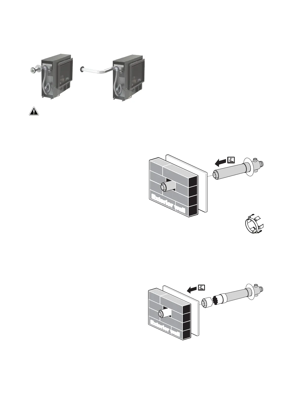
Flueing options
Creating a direct ue installation for wall less than 385 mm
1. Create the wall penetration. Allow for a continuous 2 ° fall from the heater connection point to
the wall terminal.
2. Slide the internal wall plate over the
terminal end of the ASPDFK pipe until it is
nested on the raised ring of the transition.
Pass the ASPDFK through the internal wall
penetration until the internal wall plate is
ush with the wall.
3. Create the wall terminal, refer p. 41.
4. Move the Linear into place and connect
the heater ue pipe to the ue. This is
done with the ue slide stopper provided with the ue kit.
Creating a direct extended ue installation for a wall greater than 385 mm
1. Create the wall penetration. Allow for a continuous 2 ° fall from the heater connection point to
the wall terminal.
2. Join the ue pipe to the ASPDFK, cutting is not required. The joints between ASPDFK and the
ue pipe MUST BE secured by screws through the outer pipes to prevent disconnection.
3. Follow steps 2-4 as outlined in the
previous section for creating a direct ue
installation.
E
x
t
e
r
i
o
r
wa
l
l
E
x
t
e
r
ior
w
a
ll
300 mm minimum of straight ue is required before any bends. This is required due to heat
produced from the initial section of the ue.
IMPORTANT
 Loading...