GD-70D - 24 -
<Wiring to the Terminal Plate>
● 4 - 20 mA/NT/EA Specification
●LN Specification
NOTE
For a 3-wire type 4 - 20 mA, terminal 2 is used as common for the power supply and the 4-20 mA output.
Therefore, wiring should be connected to terminals 1, 2, and 3 only. Terminal 4 can be left open.
For the NT specification, terminals 3 and 4 are not used.
For the EA specification with PoE connection, terminals 1 and 2 are disabled.
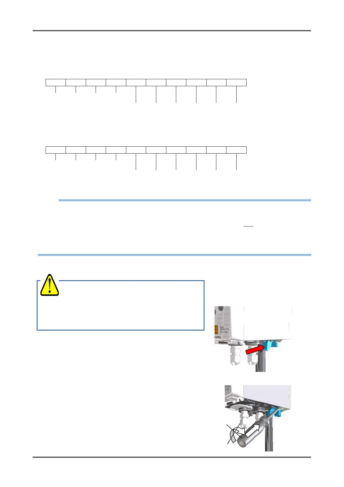
1. Make sure power to the detector is turned off.
2. While pushing the blue lever toward the mounting plate,
push the main unit up.
3. If you cannot move the main unit, insert a larger flathead
screwdriver into the mounting plate while pushing the lever
as shown to the right. Do not rotate or move the flathead
screwdriver. Simply insert it into the mounting plate.
CAUTION
• The right tools must be used.
• Only one wire can be connected to each wiring hole.
• Do not connect a wire anywhere other than a wiring hole.
 Loading...