Rockwell Automation Publication 1756-UM004D-EN-P - August 2022 25
Chapter 2 Connect to the EtherNet/IP Network
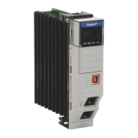
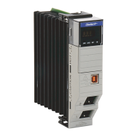
1756-EN4TR Mode Rotary Switch
The rotary switch in the upper left corner of the module is reserved for DLR,
PRP, and redundancy features.
• For modules built with firmware revision 4.001 or later, the default
position of the switch is 0.
• For modules built with firmware revision 3.002 and earlier, the default
position of the switch set to 9 for DLR, linear, or star topologies.
• The switch must be set to 7 for a redundant adapter with DLR or star
topologies.
• The switch must be set to 6 for a redundant adapter with PRP.
• Set the switch to the appropriate mode according to Table 6
.
If the switch is in a position that is not implemented, the module displays
the message “Unsupported mode. Change rotary switch setting” on the
status display. The module does not respond on any port until the mode
switch is set to the correct position and is power-cycled.
Table 6
shows the capabilities of the mode rotary switch.
Other Methods to Set the
Address
The modules support the following additional methods to change the IP
address:
• RSLinx® Classic software
• EtherNet/IP Commissioning Tool
• FactoryTalk® Linx Network Browser software
• Studio 5000 Logix Designer® Application
• Using Secure Digital Card (1756-EN4TR only)
• For more information on how to use these methods, see EtherNet/IP
Network Configuration Manual, publication ENET-UM006
.
Reset the Module to Factory
Default Value
You can reset the configuration of the module to its factory default value with
the following method.
If the module has rotary switches, set the switches to 888 and cycle power.
ATTENTION: If the mode rotary switch is set to 9 (DLR), and you insert
the module into a PRP network, it can disable the network because it
will directly connect PRP LAN A and PRP LAN B.
Table 6 - Mode Rotary Switch Capabilities
Switch Position Capability
9 DLR or Single-port
8 PRP or Single-port
7 Redundant Adapter and DLR or single-port topologies
6 Redundant Adapter and PRP or single-port topologies
IMPORTANT If you use a redundant adapter pair, the mode rotary switches of both
modules in the redundant adapter pair must be set to the same value.

 Loading...


