50 Rockwell Automation Publication 1794-UM061B-EN-P - March 2020
Chapter 5 Configure FLEX I/O Digital Modules on a DeviceNet Network
Add the Scanner to the I/O
Configuration of the
Controller Using RSLogix
5000 Software
To access the data of your network, add the scanner to the I/O configuration of
the controller.
To add a scanner:
If You Need to Conserve EtherNet/IP or ControlNet Network
Bandwidth
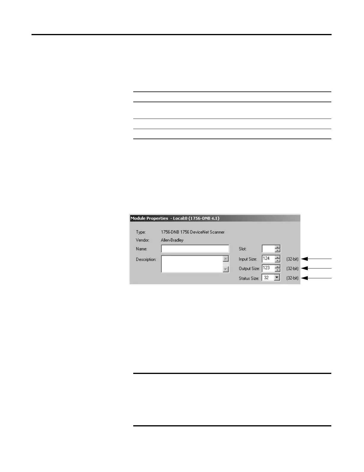
The default configuration of the scanner gives you the maximum amount of
input, output, and status data.
If the scanner communicates with the controller via an EtherNet/IP or
ControlNet network and you must conserve bandwidth over that network,
consider reducing the input, output, or status sizes.
• Set the input and output sizes = the number of input and output DINTs in
the scanner that actually store device data.
•If you are not going to use all the status information, set the status size to
the minimum required. See Set the status size for a scanner on page 51.
Step: See page:
❑ If You Need to Conserve EtherNet/IP or ControlNet Network
Bandwidth
50
❑ Add the Scanner to the I/O Configuration Folder 52
❑ Define the Properties of the Scanner 53
Set the status size for a scanner
•If you want to only use the ASCII representation of
scanner status/display, then set the Status Size = 10.
• If you also want to read the status code of the scanner, set
the Status Size = 11.

 Loading...


