Rockwell Automation Publication 2198-UM005C-EN-P - February 2022 137
Chapter 6 Configure and Start up the Kinetix 5300 Drive System
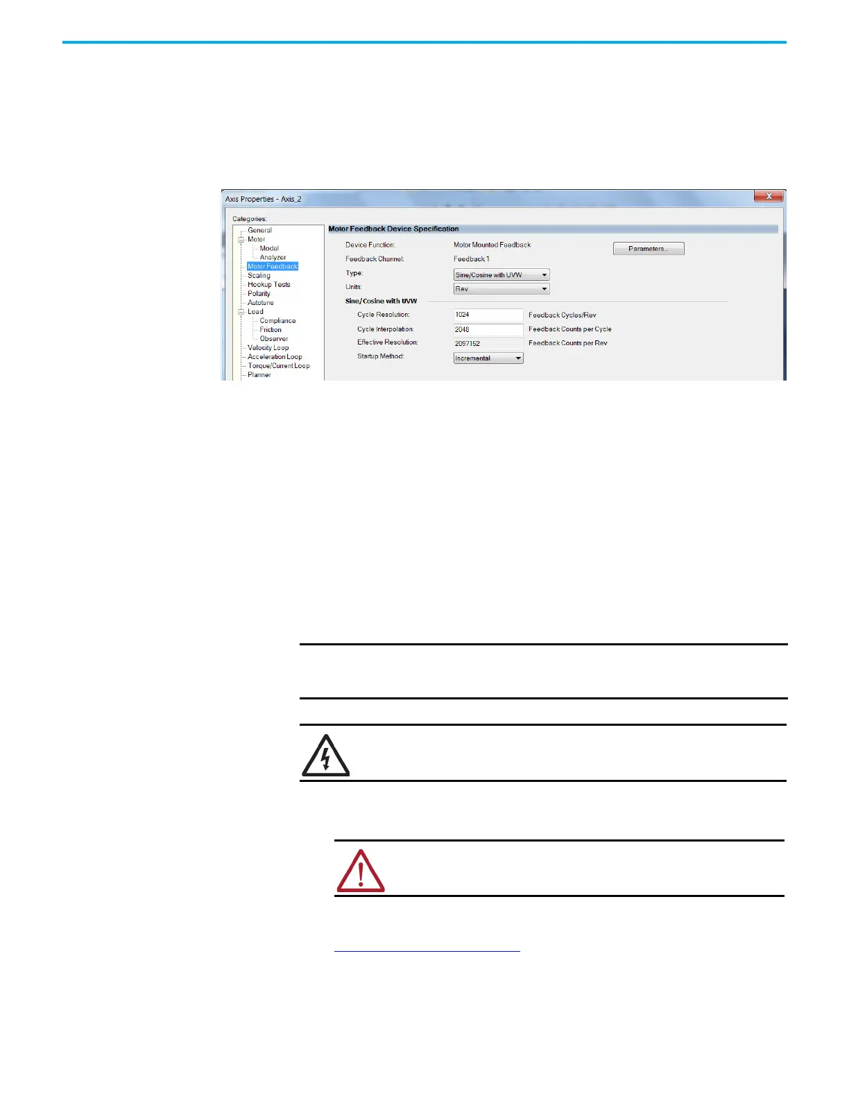
Sine/Cosine with Hall Feedback
In this example, a motor feedback device is configured for Sine/Cosine with
UVW feedback.
1. In the Controller Organizer, right-click an axis and choose Properties.
2. Select the Motor Feedback category.
The Motor Feedback Device Specification dialog box appears.
3. Configure the device function and type.
In this example, Motor Feedback is the device function and Sine/Cosine
with UVW is the feedback type.
4. Enter values for the Sine/Cosine with UVW specification fields.
The only valid values for Cycle Interpolation are powers of 2 from 4
through 65536.
5. From the Startup Method pull-down menu, choose Incremental.
6. From the Alignment pull-down menu, choose Not Aligned.
7. Click OK.
Apply Power to the
Kinetix 5300 Drive
This procedure assumes that you have wired and configured your Kinetix 5300
system and your Logix 5000 controller.
Follow these steps to apply power to the Kinetix 5300 system.
1. Disconnect the load to the motor.
2. Apply 24V DC control power.
The four-segment status display begins the startup sequence. Refer to
Startup Sequence
on page 104. If the startup sequence does not begin,
check the 24V control power connections.
3. When the startup sequence completes, verify that the two status
indicators are steady green and the four-character stats displays -03-,
meaning the axis state is in Pre-charge.
IMPORTANT When 24V power is first applied, the fan turns on for a few seconds and
then, off. It only turns back on if the drive is above a factory configured
temperature threshold or the drive is enabled.
SHOCK HAZARD: To avoid hazard of electrical shock, perform all mounting and
wiring of the Kinetix 5300 servo drives prior to applying power. After power is
applied, connector terminals can have voltage present even when not in use.
ATTENTION: To avoid personal injury or damage to equipment,
disconnect the load to the motor. Make sure each motor is free of all
linkages when initially applying power to the system.

 Loading...


