42 Rockwell Automation Publication 2198-UM005C-EN-P - February 2022
Chapter 3 Mount the Kinetix 5300 Drive System
Determine Mounting Order When drives are mounted by using the zero-stack feature, they must be
mounted from left to right in descending frame-size order. For the drives to
engage properly (when more than one frame size exists in the drive system)
frame 3 drives must mount left of frame 1 or 2 drives, and frame 2 drives must
mount left of frame 1 drives.
Zero-stack Tab and Cutout
Engaging the zero-stack tab and cutout from drive-to-drive makes efficient
use of panel space for installations with multiple drives.
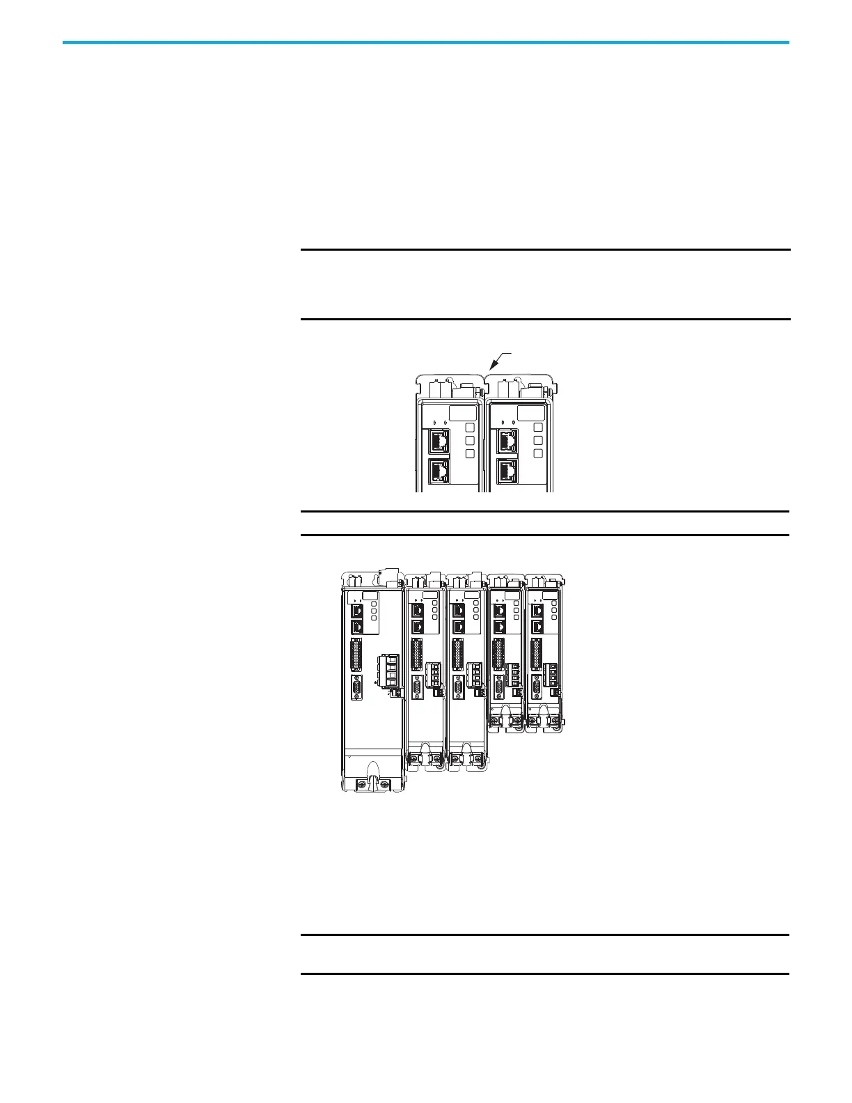
Figure 17 - Zero-stack Tab and Cutout Example
Figure 18 - Drive Mounting Order Example
Shared-bus Connection System
The shared-bus connection system is used to extend 24V control input from
drive-to-drive in shared-bus configurations.
IMPORTANT Engaging the zero-stack tab and cutout from drive-to-drive is required for
24V DC shared-bus drive configurations. This is done to make sure the
drive connectors are spaced properly to accept the bus-bars and
T-connectors.
2198-Cxxxx-ERS Drives
(front view)
Zero-stack Tab and Cutout Engaged
IMPORTANT Mount drives in descending order, left to right, according to frame size.
MBRK
1
10
1
2
MFB
U
V
W
MBRK
W
V
U
1
2
MFB
MBRK
W
V
U
1
10
1
2
MBRK
1
10
1
2
MFB
U
V
W
MBRK
1
10
1
2
MFB
U
V
W
1
10
2198-Cxxxx-ERS Drive System
(front view)
Frame 3
Drive
Frame 2
Drives
Frame 1
Drives
IMPORTANT When the shared-bus connection system is used, the zero-stack tab and
cutout must be engaged between adjacent drives.

 Loading...


