96 Rockwell Automation Publication 2198-UM005C-EN-P - February 2022
Chapter 5 Connect the Kinetix 5300 Drive System
External Passive-shunt
Resistor Connections
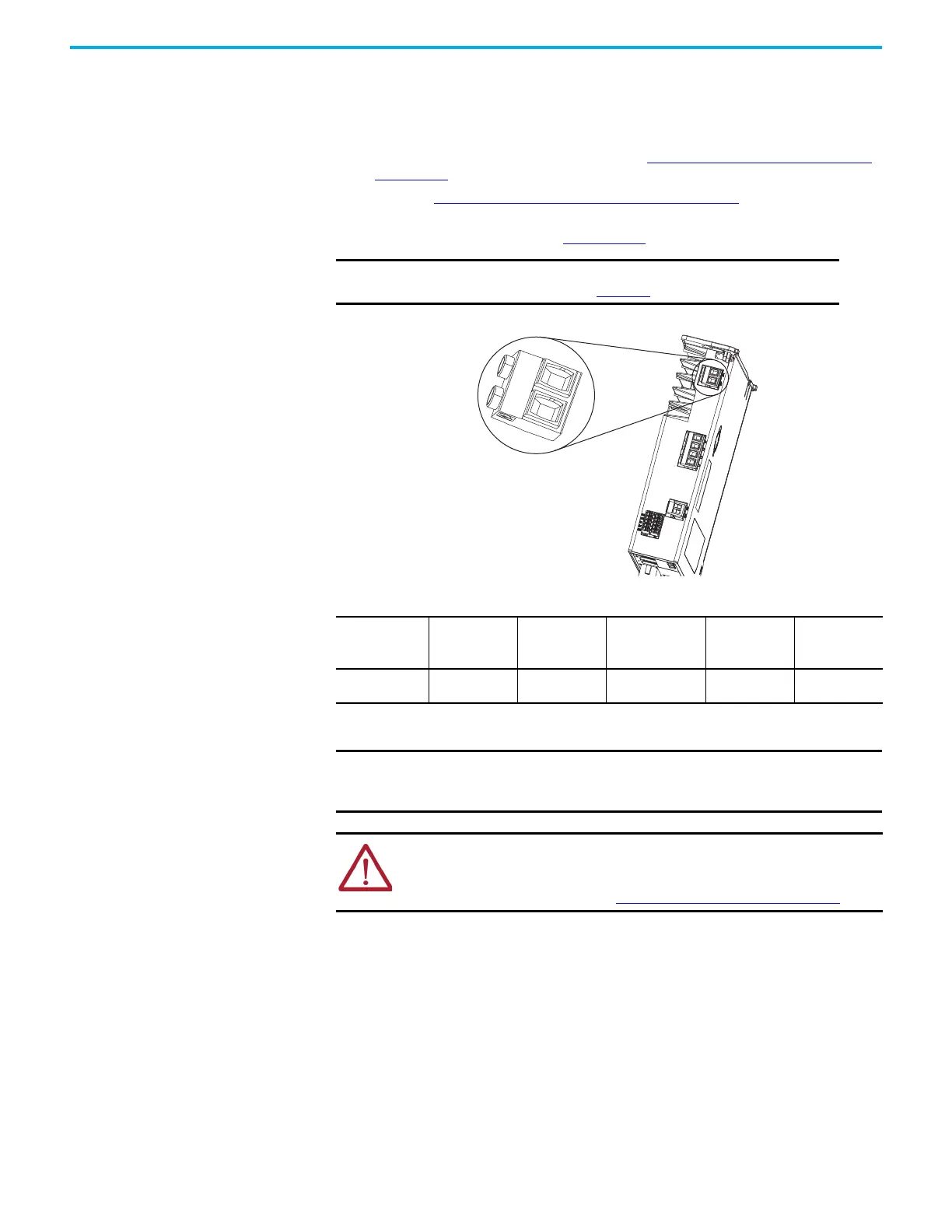
Passive shunt connections are made at the shunt connector on the top of the
drive.
Follow these guidelines when wiring your 2097-Rxxx shunt resistor:
• For noise zone considerations, refer to External Passive Shunt Resistor
on page 39.
• Refer to Shunt Resistor Wiring Example
on page 172.
• Refer to the installation instructions provided with your Bulletin 2097
shunt resistor, publication 2097-IN002
.
Figure 52 - Shunt Connector Wiring
Table 57 - Shunt Resistor Connector Specifications
IMPORTANT To improve system performance, run wires and cables in the
wireways as established in Chapter 2.
Kinetix 5300 Drive
Top View
Shunt Connector
Drive Cat. No.
Pin
(1)
(1) Pin numbering is not used on the shunt connector. Shunt connections to the 2-pin connector is arbitrary.
Signal
Recommended
Wire Size
mm
2
(AWG)
Strip Length
mm (in.)
Torque Value
N•m (lb•in)
2198-Cxxxx-ERS —
DC+
SH
0.2…2.5
(24…12)
8.0 (0.31)
0.5…0.6
(4.4…5.3)
IMPORTANT You must unplug the internal shunt connector plug before connecting the
external shunt-resistor wires. Use the spare shunt connector plug provided
with the drive for the external shunt.
ATTENTION: Your internal or external passive shunt requires configuration in
the Logix Designer application. Failure to properly configure the shunt can result
in reduced performance or shunt resistor damage. For Module Properties >
Power category configuration, see Continue Drive Configuration
on page 112.

 Loading...


