Rockwell Automation Publication 2198-UM005C-EN-P - February 2022 95
Chapter 5 Connect the Kinetix 5300 Drive System
Table 54 - 2090-CFBM6DF-CBAAxx Feedback Cables
Table 55 - 2090-DANFCT-Sxx Feedback Cables
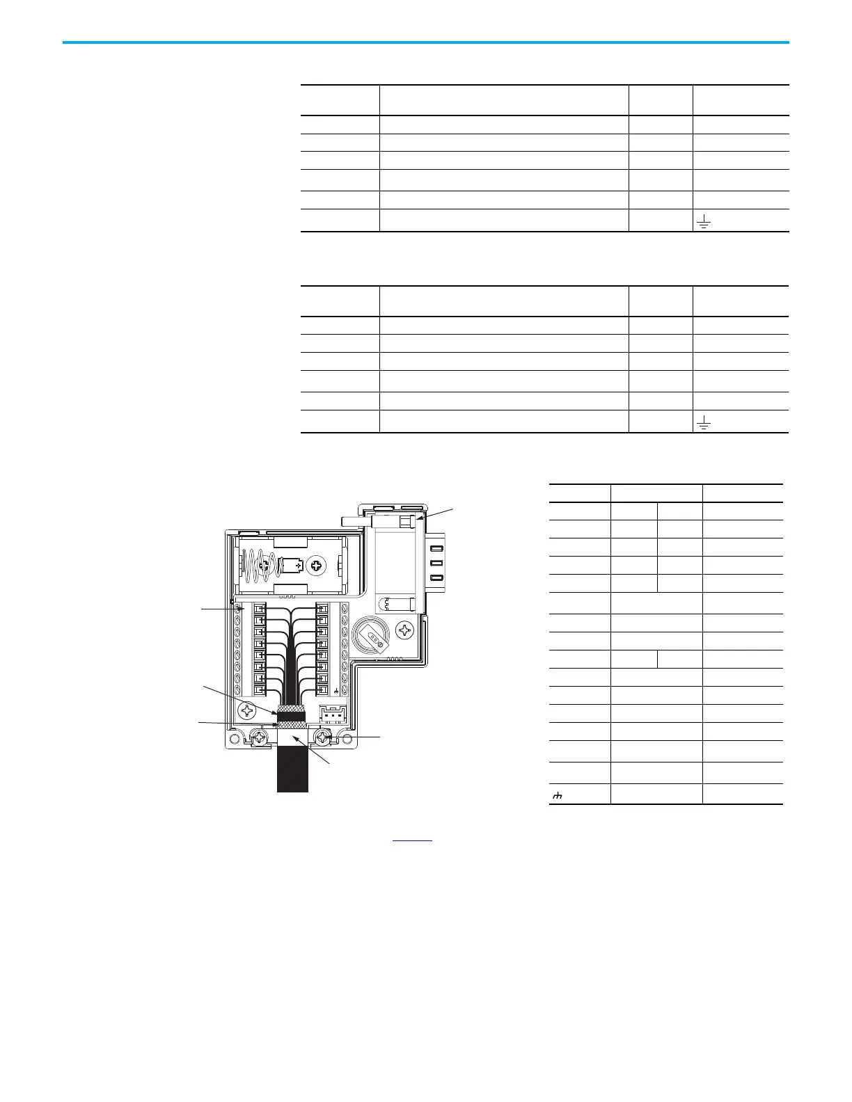
Figure 51 - Wire the 2198-K53CK-D15M Feedback Connector Kit
Motor Pin
TLY-Axxxx-B
17-bit Absolute, Multi-turn, High-resolution Feedback
Wire Color
2198-K53CK-D15M
Connector Kit Pin
13 DATA+ Green 5
14 DATA– White/Green 10
22 EPWR_5V Gray 14
23 ECOM and BAT- White/Gray
6
(1)
(1) BAT- is tied to ECOM (pin 23) in the cable.
6 BAT+ Orange BAT+
24 Drain —
Motor Pin
TL-Axxxx-B
17-bit Absolute, Multi-turn, High-resolution Feedback
Wire Color
2198-K53CK-D15M
Connector Kit Pin
12 SD+ Brown 5
13 SD– White/Brown 10
7EPWR_5V Gray14
8 ECOM and BAT- White/Gray
6
(1)
(1) BAT- is tied to ECOM (pin 8) in the cable.
14 BAT+ Orange BAT+
9Drain —
Shield Clamp
2198-K53CK-D15M
Connector Kit
Clamp Screws (2)
Tie wrap is required to
create a high-frequency
bond between shield and
ground pad, stress relief,
and wire management.
Exposed shield aligned over
ground pad and under the
shield clamp.
8-pin
Connector (2x)
15-pin D-sub to
Motor Feedback (MFB)
Connector
Kinetix 2090
Feedback Cable
Mounting
Screw
For more information on wiring the 2198-K53CK-D15M, see Kinetix 5300 Feedback
Connector Kit Installation Instructions, publication 2198-IN023
.
Terminal Signal Wire Color
1 SIN+ AM+ Black
2 SIN– AM– White/Black
3 COS+ BM+ Red
4 COS– BM– White/Red
5 DATA+ IM+ Green
6
ECOM
(1)
(1) The ECOM and TS- connections are tied together and
connect to the cable shield.
White/Gray
7EPWR_9VOrange
8S3 White/Yellow
10 DATA– IM– White/Green
11 TS+ White/Orange
12 S1 White/Blue
13 S2 Yellow
14 EPWR_5V Gray
+Battery +
—
(2)
(2) See cable pinouts for wire colors.
–Battery –
—
(2)
Drain Shield

 Loading...


