112 Rockwell Automation Publication 2198-UM005C-EN-P - February 2022
Chapter 6 Configure and Start up the Kinetix 5300 Drive System
Continue Drive Configuration
After you’ve established your Kinetix 5300 drive in the Studio 5000 Logix
Designer application, the remaining configuration steps are the same
regardless of the drive catalog number.
For the Kinetix 5300, two axes are supported.
• Axis 1 applies to the Motor Feedback connector (MFB)
• Axis 2 applies to the Digital Inputs and Auxiliary Feedback connector.
See Table 26 on page 60
for the location of the connectors and refer to
Understand Control Signal Specifications on page 56 for additional
information about the connector functions.
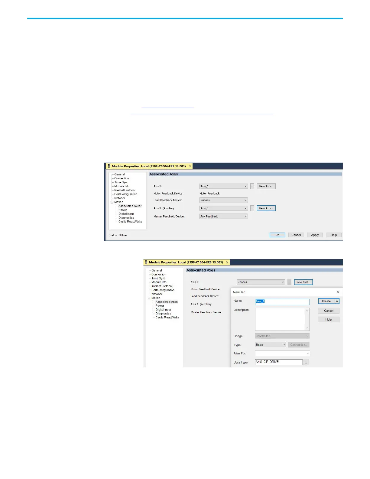
Follow these steps to configure the associated axes.
1. Right-click the 2198-Cxxxx-ERS servo drive you just created and choose
Properties.
2. Click Associated Axes.
3. Click New Axis.
The New Tag dialog box appears.

 Loading...


