156 Rockwell Automation Publication 2198-UM005C-EN-P - February 2022
Chapter 8 Remove and Replace Servo Drives
Remove and Replace
Kinetix 5300 Servo Drives
Follow these steps to remove and replace servo drives from the panel.
Remove Power and All Connections
1. Verify that all control and input power has been removed from the
system.
2. Wait five minutes for the DC bus to discharge completely before
proceeding.
3. Label and remove all wiring connectors from the drive you are removing.
To identify each connector, refer to Kinetix 5300 Connector Data
on
page 52.
4. If used, remove the 24V shared-bus input wiring connector,
T-connector, and bus-bar from the drive you are removing.
Refer to Shared-bus Connection System
on page 42.
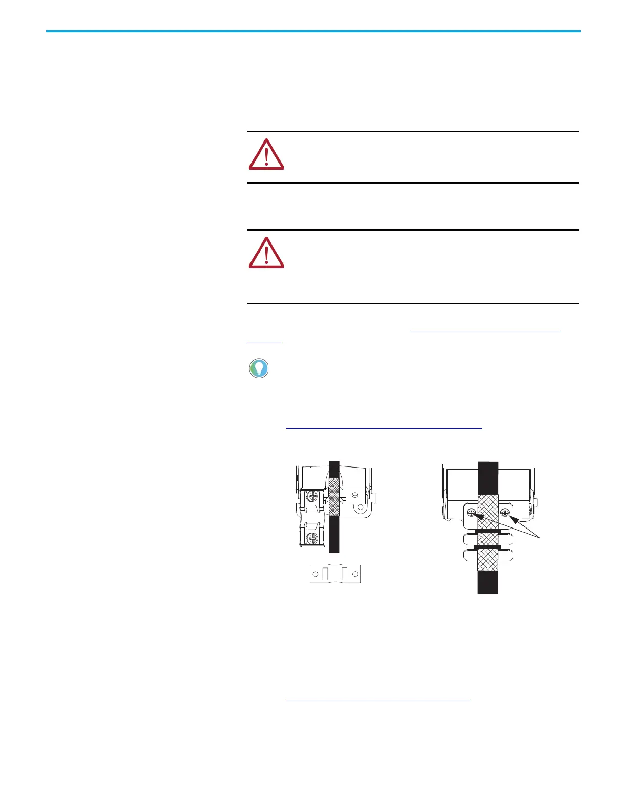
5. Use a screwdriver to loosen or remove the two cable clamp screws, as
needed.
All drives are equipped with a standard clamp. Remove one or both
screws as needed. However, for Frame 3 clamping plate, remove both
screws and transfer the clamping plate to the new Frame 3 drive.
6. Remove the motor power cable from the cable shield clamp.
7. Unplug the motor feedback cable connector or 2198-K53CK-D15M
connector kit from the MFB connector.
8. Remove the ground screw and braided ground strap.
Refer to Ground the System Subpanel
on page 71.
ATTENTION: To avoid shock hazard or personal injury, make sure that
all power has been removed before proceeding. This system can have
multiple sources of power. More than one disconnect switch can be
required to de-energize the system.
SHOCK HAZARD: This product contains stored energy devices. To avoid
the hazard of electrical shock, verify that voltage on capacitors has been
discharged before attempting to service, repair, or remove this unit. Do
not attempt the procedures in this document unless you are qualified to
do so and are familiar with solid-state control equipment and the safety
procedures in publication NFPA 70E.
You do not need to remove the shunt connector, unless there is an
external shunt wired to it.
Motor Cable
Motor Cable
Clamp Screws
Frame 3
Clamping Plate
Frame 1, 2, or 3
Standard Clamp
Clamp Spacer (if
needed)

 Loading...


