16 Rockwell Automation Publication 2198-UM005C-EN-P - February 2022
Chapter 1 Start
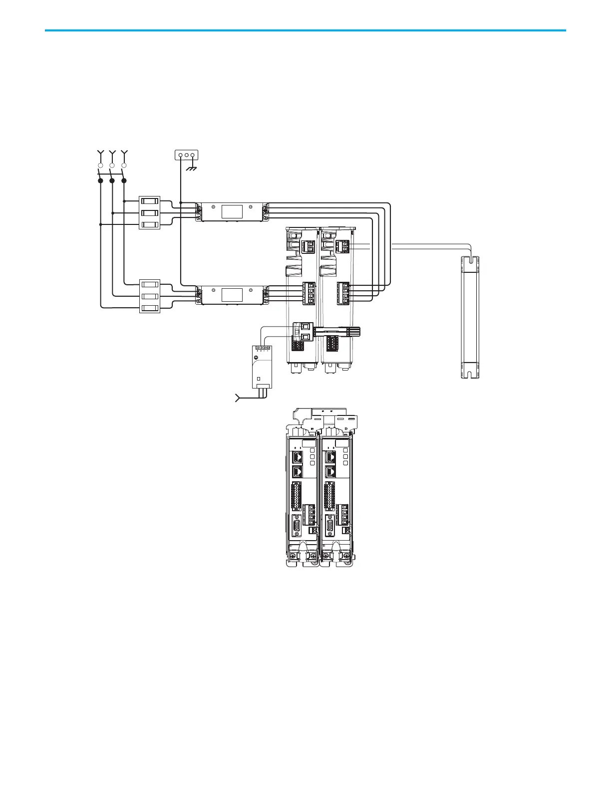
In this example, two drives are shown with input power to the standard input
connectors and control power input by using 24V shared-bus connectors.
With two or more drives in the drive configuration, each drive requires AC
input power and line filter.
Figure 2 - Typical Kinetix 5300 Installation with 24V Shared-bus Connectors
1606-XL
Power Supply
Input
Allen-Bradley
L3L2
L1
DC+ SH
SB+
SB-
S1
SC
S2
MBRK
W
V
U
1
10
1
2
MFB
L3L2
L1
DC+ SH
SB+
SB-
S1
SC
S2
MBRK
W
V
U
1
10
1
2
MFB
Single-phase or
Three-phase
Input Power
Line
Disconnect
Device
Circuit
Protection
2097-Rx or 2198-Rxxxx
Shunt Resistor
(optional component)
2198-Cxxxx-ERS Drives
(top view)
AC Input Power
Bonded Cabinet
Ground Bus
2198-DB08-F or
2198-DBRxx-F
AC Line Filter
(required for CE)
Shared 24V (control power input)
2198-H0x0-x-x shared-bus connection
system for 24V bus-sharing configurations.
AC Input Wiring
Connectors
1606-XLxxx
24V DC Control, Digital Inputs,
and Motor Brake Power
(customer-supplied)
2198-Cxxxx-ERS Drives
(front view)
2198-DB08-F or
2198-DBRxx-F
AC Line Filter
(required for CE)
Circuit
Protection

 Loading...


