uses a power/brake cable. Flying-lead feedback connections to the
, for more information.
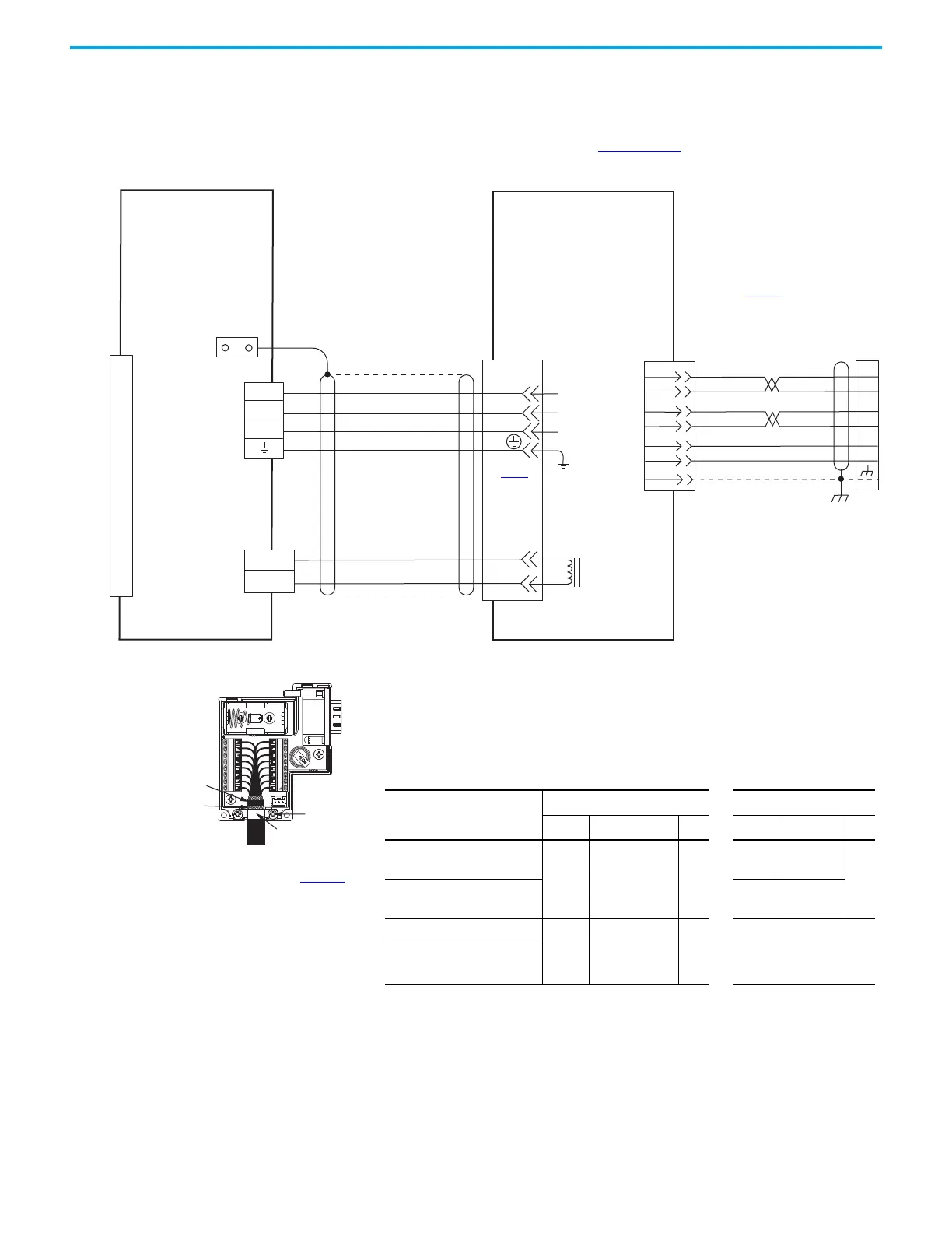
Motor Brake
Connector
Motor Power
Connector
2198-Cxxxx-ERS
Kinetix 5300 Drives
TLP-A/B115, TLP-A/B145-050,
TLP-A145-090, TLP-A/B145-100,
TLP-A/B145-150, TLP-B145-200,
TLP-A/B145-250,
TLP-A200-200, TLP-A/B200-300,
TLP-A200-350, TLP-A/B200-450
Servo Motors with
High-resolution Feedback
Motor Feedback
(MFB) Connector
Motor Power
Connector
Motor
Feedback
Connector
See connector kit
illustration (below)
for proper ground technique.
Use the 2198-K53CK-D15M
feedback connector kit when
building your own cables.
Ground Technique for
Feedback Cable Shield
360° exposed shield that
is secured under clamp.
Clamp Screws (2)
Clamp
See table on page 169 for note information.
2090-CTFB-MFDD-CFAxx (standard) and
2090-CTFB-MFDD-CFFxx (continuous-flex)
feedback cables do not require the
2198-K53CK-D15M feedback connector kit.
BROWN
BLUE
WHITE
WHT/RED
SHIELD
RED
WHITE
BLACK
GREEN/YELLOW
BROWN/RED
BLUE/BLACK
2090-CTPB-MxDF-xxAxx
(standard) or
2090-CTPB-MxDF-xxFxx
(continuous-flex)
Motor Power Cable
Tie Wrap
RED
BLACK
Cable Shield
Clamp
Note 5
Table 89 - Motor and Brake Cable Pinouts
Motor Power/Brake Cable
Cat. No.
Motor Power Motor Brake
Signal Wire Color Pin Signal Wire Color Pin
2090-CTPx-MCDF-12
U
V
W
PE
RED
WHITE
BLACK
GREEN/YELLOW
F
I
B
E
BR+
BR–
RED
BLACK
G
H
2090-CTPx-MCDF-16
BR+
BR–
BROWN
BLUE
2090-CTPx-MDDF-08 U
V
W
PE
RED
WHITE
BLACK
GREEN/YELLOW
D
E
F
G
BR+
BR–
RED
BLACK
A
B
2090-CTPx-MDDF-12
See Table 88 for
motor power and
brake pinouts
2198-K53CK-D15M Feedback
Connector Kit
Refer to Kinetix 5300 Feedback Connector Kit
Installation Instructions, publication 2198-IN023
, for
connector kit specifications.

 Loading...


