40 Rockwell Automation Publication 2198-UM005C-EN-P - February 2022
Chapter 2 Plan the Kinetix 5300 Drive System Installation
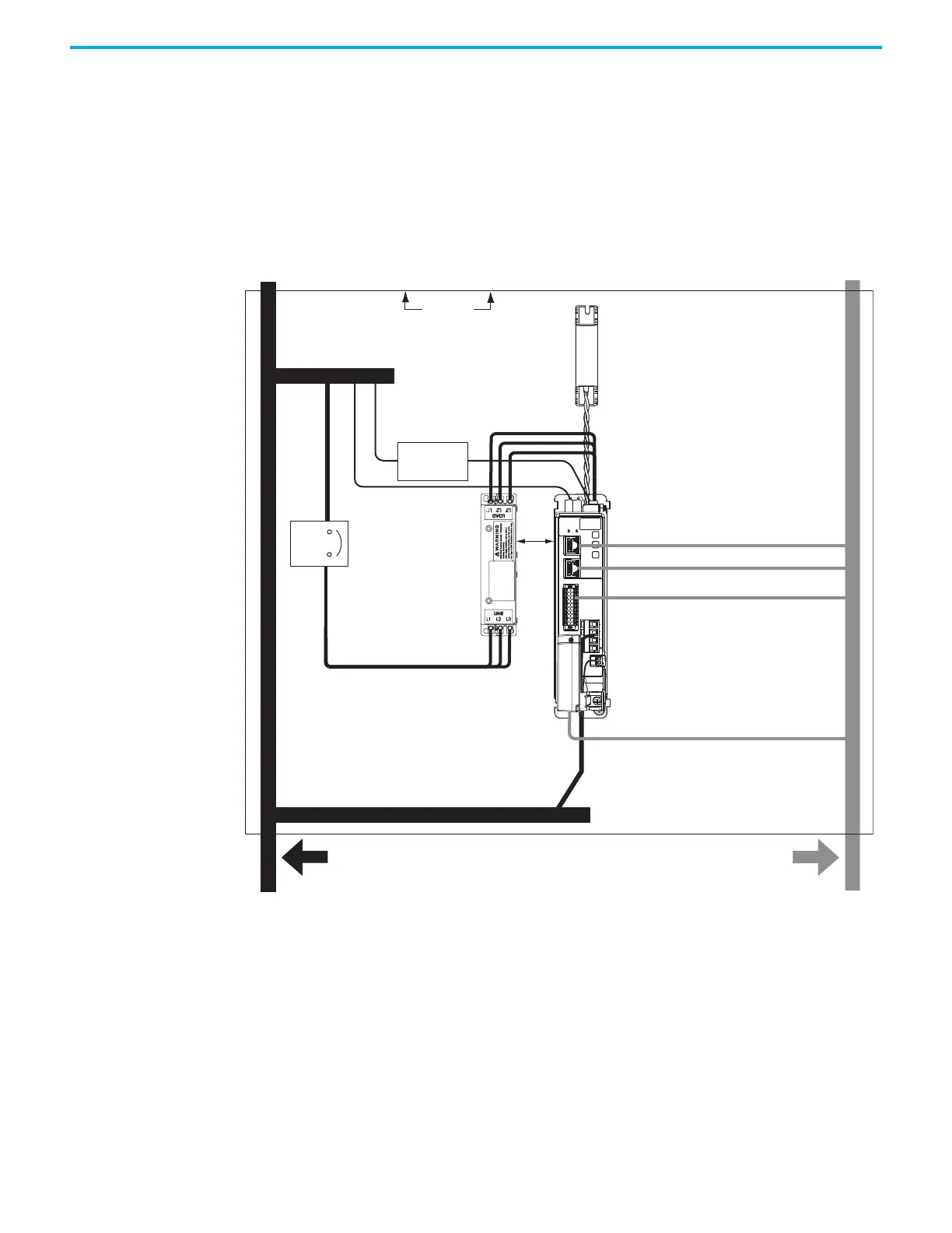
When mounting your Bulletin 2097 or Bulletin 2198 passive-shunt resistor
inside the enclosure, follow these additional guidelines:
• Mount metal-clad modules anywhere in the dirty zone, but as close to the
Kinetix 5300 drive as possible.
• Route shunt power wires with other very dirty wires.
• Keep unshielded wiring as short as possible. Keep shunt wiring as flat to
the cabinet as possible.
• Separate shunt power cables from other sensitive, low voltage signal
cables.
Figure 16 - External Shunt Resistor Inside the Enclosure
C
D
D
D
D
C
MBRK
W
V
U
1
10
1
2
MFB
VD
D
50 mm
(1.97 in.)
Dirty Wireway
Clean Wireway
Motor Power Cable
Very Dirty Connections Segregated (not
in wireway)
Enclosure
No sensitive equipment
within
150 mm (6.0 in.).
Shunt Power Wiring Methods:
Twisted pair in conduit (1st choice).
Twisted pair, two twists per foot (min) (2nd choice).
Circuit
Protection
Route single motor cables
in shielded cable.
Route registration and communication
signals in shielded cables.
24V DC
Power Supply
AC Line Filter
(required for CE)
150 mm (6.0 in.)
clearance (min) on all four sides
of the shunt resistor.
Hardwired Safety Cable
Motor Feedback Cable
Ethernet Cable
(shielded)
I/O Cable

 Loading...


