EasyManuals Logo

Rockwell Automation Allen-Bradley Kinetix 5300 User Manual

Rockwell Automation Allen-Bradley Kinetix 5300
246 pages
To Next Page IconTo Next Page
To Previous Page IconTo Previous Page
Page #47 background imageLoading...
Page #47 background image
Rockwell Automation Publication 2198-UM005C-EN-P - February 2022 47
Chapter 3 Mount the Kinetix 5300 Drive System
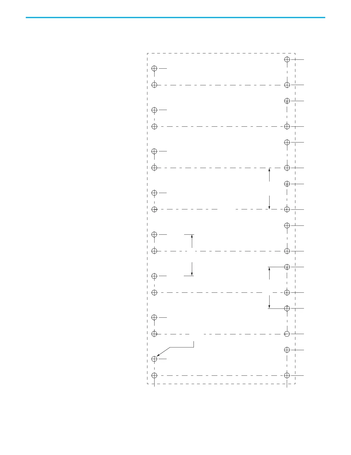
This hole pattern applies when all drives in the system are frame 3 drives.
There are 85.20 mm between mounting holes, as shown.
Figure 23 - Frame 3 Hole Pattern
273.70
0
52.50
85.20
137.70
0
170.40
222.90
255.60
308.10
340.80
393.30
426.0
478.50
511.20
563.70
596.40
648.90
Axis 1 Axis 2 Axis 3 Axis 4
Axis 5 Axis 6 Axis 7 Axis 8
32x
ØM4 (#8-32)
34.00
119.20
204.40
289.60
374.80
460.0
545.20
630.40
85.20
85.20
85.20
Hole spacing is measured in millimeters and not
converted to inches to avoid errors due to rounding.

Table of Contents

Other manuals for Rockwell Automation Allen-Bradley Kinetix 5300

Questions and Answers:

Question and Answer IconNeed help?

Do you have a question about the Rockwell Automation Allen-Bradley Kinetix 5300 and is the answer not in the manual?

Rockwell Automation Allen-Bradley Kinetix 5300 Specifications

General IconGeneral
BrandRockwell Automation
ModelAllen-Bradley Kinetix 5300
CategoryServo Drives
LanguageEnglish

Related product manuals