EasyManuals Logo

Rockwell Automation Allen-Bradley Kinetix 5300 User Manual

Rockwell Automation Allen-Bradley Kinetix 5300
246 pages
To Next Page IconTo Next Page
To Previous Page IconTo Previous Page
Page #49 background imageLoading...
Page #49 background image
Rockwell Automation Publication 2198-UM005C-EN-P - February 2022 49
Chapter 3 Mount the Kinetix 5300 Drive System
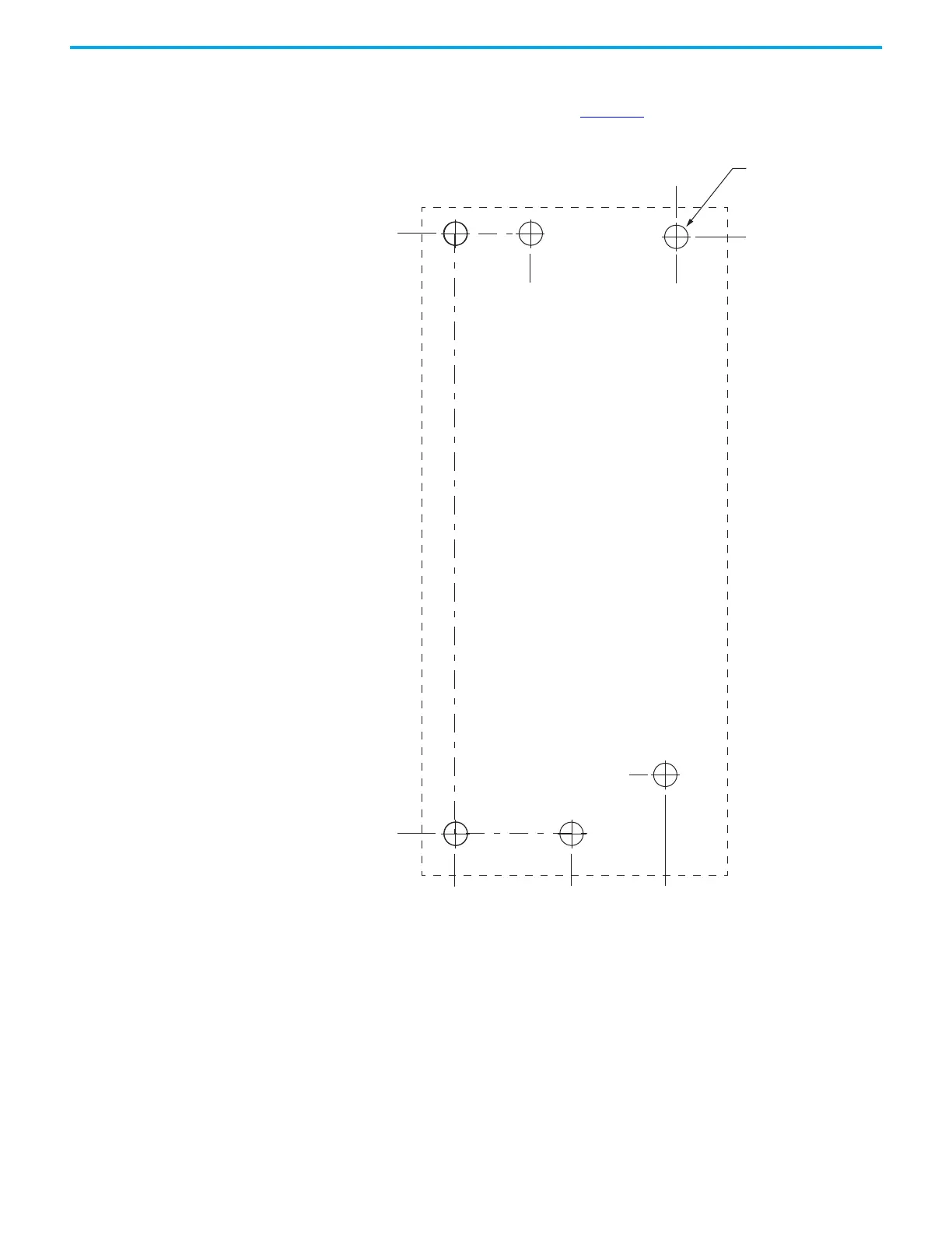
This hole pattern applies when transitioning from frame 3 drives to frame 2
drives. To mount additional frame 2 drives to the right of Axis 2 in this figure,
refer to the frame 2 hole pattern in Figure 21
.
Figure 25 - Frame 3 to Frame 2 Hole Pattern
273.70
0
52.50
0
6x
ØM4 (#8-32)
Axis 1
(frame 3)
Axis 2
(frame 2)
272.24
28.40
95.00
100.00
34.00
Hole spacing is measured in millimeters
and not converted to inches to avoid errors
due to rounding.

Table of Contents

Other manuals for Rockwell Automation Allen-Bradley Kinetix 5300

Questions and Answers:

Question and Answer IconNeed help?

Do you have a question about the Rockwell Automation Allen-Bradley Kinetix 5300 and is the answer not in the manual?

Rockwell Automation Allen-Bradley Kinetix 5300 Specifications

General IconGeneral
BrandRockwell Automation
ModelAllen-Bradley Kinetix 5300
CategoryServo Drives
LanguageEnglish

Related product manuals