136 Rockwell Automation Publication 2080-UM002L-EN-E - November 2021
Chapter 8 Use the High-Speed Counter and Programmable Limit Switch
This bit is transitional and is set by the HSC sub-system. It is up to the control
program to utilize, track if necessary, and clear (0) the underflow condition.
Underflow conditions do not generate a controller fault.
The Count Direction status flag is controlled by the HSC sub-system. When the
HSC accumulator counts up, the direction flag is set (1). Whenever the HSC
accumulator counts down, the direction flag is cleared (0).
If the accumulated value stops, the direction bit retains its value. The only time
the direction flag changes is when the accumulated count reverses.
This bit is updated continuously by the HSC sub-system whenever the
controller is in a run mode.
The High Preset Reached status flag is set (1) by the HSC sub-system whenever
the accumulated value (HSCSTS.Accumulator) is greater than or equal to the
high preset variable (HSCAPP.HPSetting).
This bit is updated continuously by the HSC sub-system whenever the
controller is in an executing mode. Writing to this element is not
recommended.
The Low Preset Reached status flag is set (1) by the HSC sub-system whenever
the accumulated value (HSCSTS.Accumulator is less than or equal to the low
preset variable HSCAPP.LPSetting).
This bit is updated continuously by the HSC sub-system whenever the
controller is in an executing mode. Writing to this element is not
recommended.
The Overflow Interrupt status bit is set (1) when the HSC accumulator counts
through the overflow value and the HSC interrupt is triggered. This bit can be
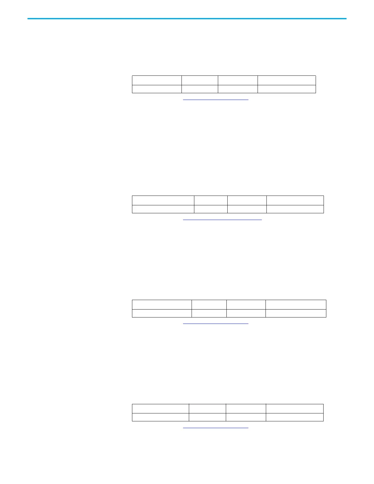
Count Direction (HSCSTS.CountDir)
Description Data Format
HSC Modes
(1)
(1) For Mode descriptions, see HSC Mode (HSCAPP.HSCMode) on page 127.
User Program Access
HSCSTS.CountDir bit 0…9 read only
High Preset Reached (HSCSTS.HPReached)
Description Data Format
HSC Modes
(1)
(1) For Mode descriptions, see Count Down (HSCSTS.CountDownFlag) on page 135.
User Program Access
HSCSTS.HPReached bit 2…9 read/write
Low Preset Reached (HSCSTS.LPReached)
Description Data Format
HSC Modes
(1)
(1) For Mode descriptions, see HSC Mode (HSCAPP.HSCMode) on page 127.
User Program Access
HSCSTS.LPReached) bit 2…9 read only
Overflow Interrupt (HSCSTS.OFCauseInter)
Description Data Format
HSC Modes
(1)
(1) For Mode descriptions, see HSC Mode (HSCAPP.HSCMode) on page 127.
User Program Access
HSCSTS.OFCauseInter bit 0…9 read/write

 Loading...


