Rockwell Automation Publication 7000L-UM301F-EN-P - March 2020 201
Commissioning Chapter 4
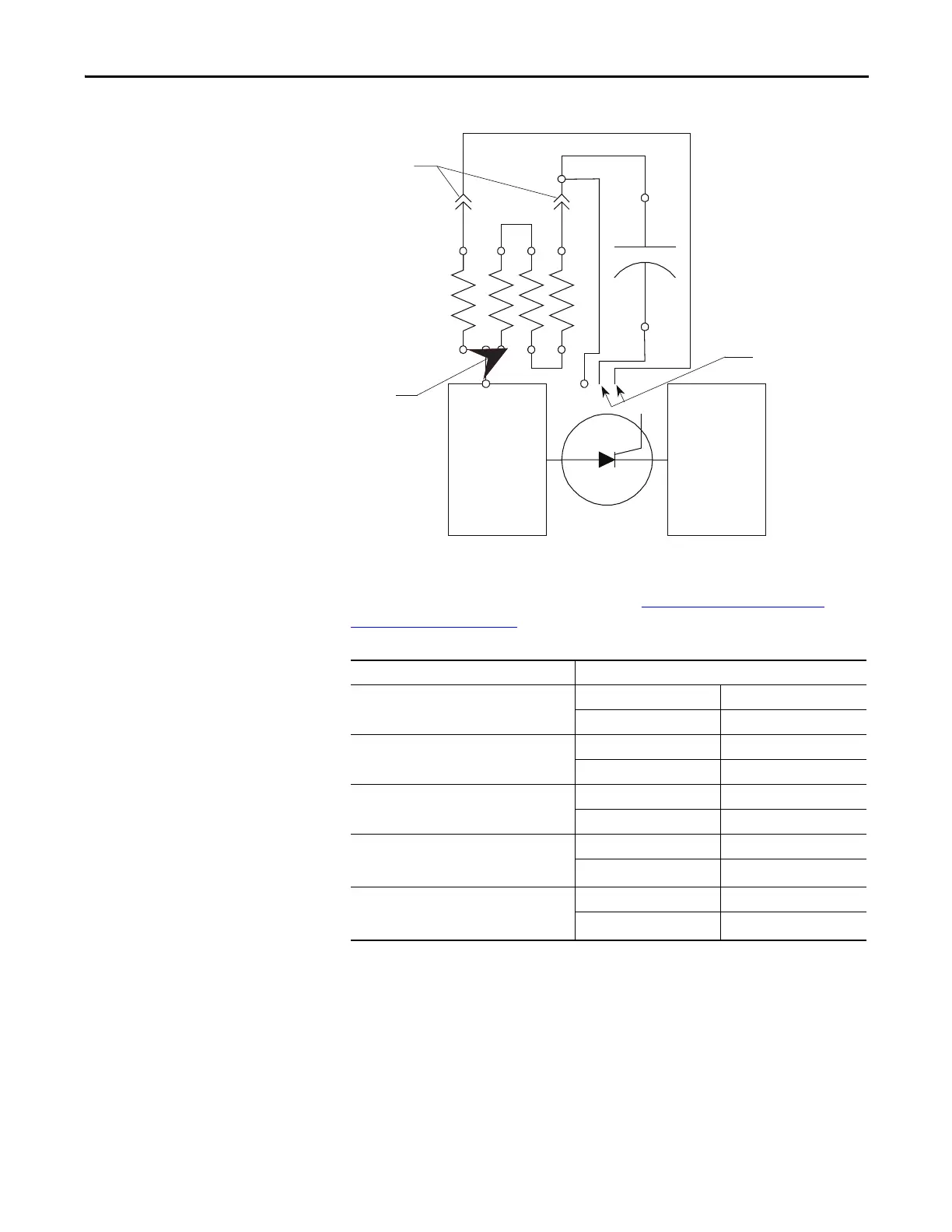
Figure 185 - SCR Snubber Circuit Connections
If a device or snubber component is found to be damaged, a detailed replacement
procedure is a located in Chapter 5 – refer to
Component Definition and
Maintenance on page 265.
SCR Anode-to-Cathode Resistance
Performing an Anode-to-cathode resistance test verifies the integrity of the SCR.
Unlike the SGCT, the SCR uses the snubber circuit to power the self-powered
gate driver boards. The resistance measurement taken across each SCR should be
consistent; an inconsistent value may indicate a damaged sharing resistor, self-
powered gate driver board or SCR.
Anode
Chillblock
Cathode
Chilblock
Disconnect Points
Rsh-1
Rsn-1
Cs-1
Cs-2
Rsn-2
To Gate Driver Board
TP
Rsh-2
SCR Resistance Measurement Measured Resistance
SCR Anode-Cathode Resistance
(Heatsink to Heatsink) k-Ω
(Lowest) (Highest)
SCR Gate-Cathode Resistance
(Across SCR Phoenix Connector) Ω
(Lowest) (Highest)
Snubber Resistance
(Test Point – Heatsink on Left) Ω
(Lowest) (Highest)
Snubber Capacitance
(Test Point – White Wire from Snubber
Phoenix connector on Right) μF
(Lowest) (Highest)
Sharing Resistance
(Red Wire from Snubber Phoenix
connector – Heatsink on Right) k-Ω
(Lowest) (Highest)

 Loading...


