Rockwell Automation Publication 7000L-UM301F-EN-P - March 2020 325
Component Definition and Maintenance Chapter 5
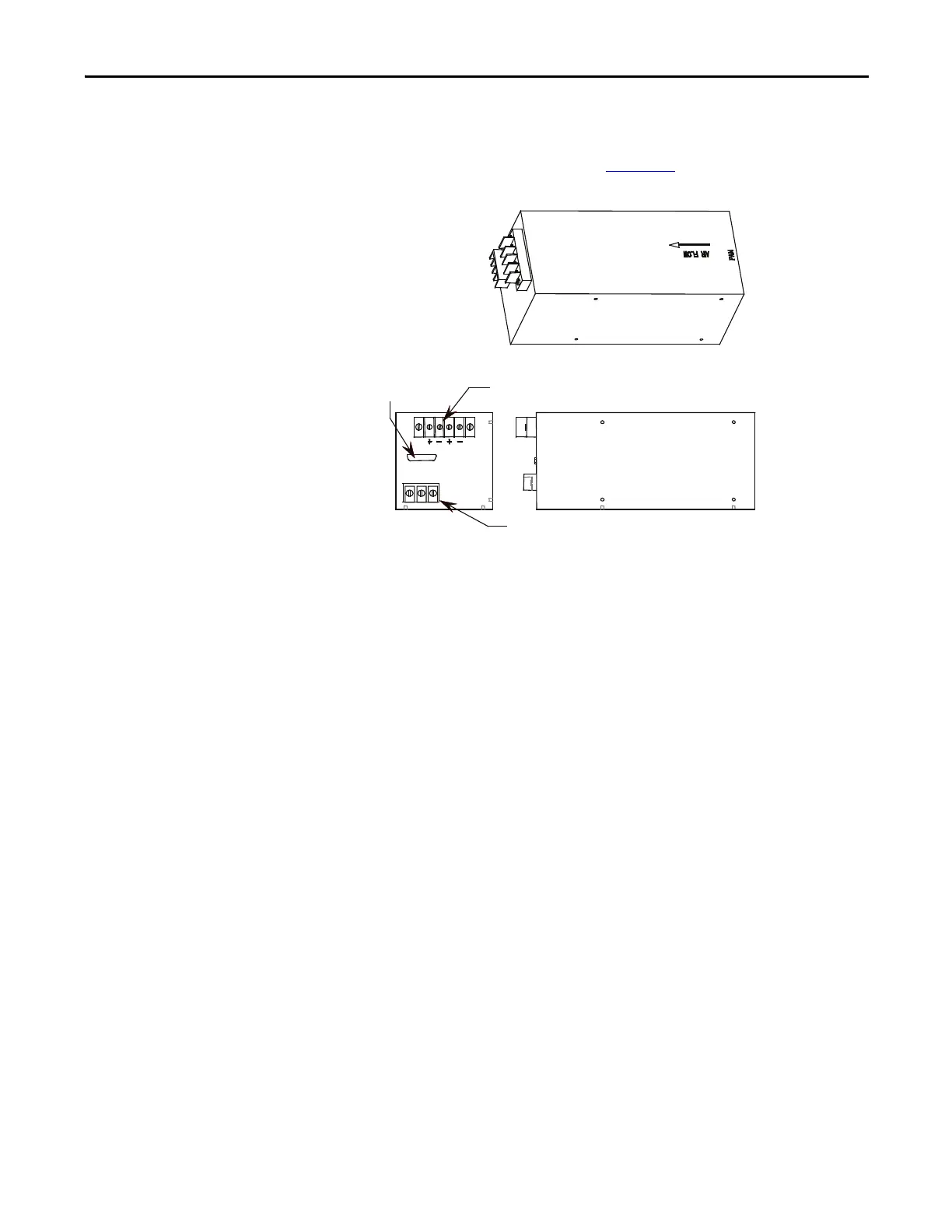
Terminal / Connections Descriptions
The terminal connections are shown in Figure 272.
Figure 272 - Terminal locations on AC/DC Pioneer power supply
Ensure the output of the supply is 56V DC.
There is a potentiometer on the top of the power supply that adjusts the 56 Volt
DC output for the power supply. Isolate the output of the power supplies;
multiple supplies in series will affect your measurements. With the control power
on and the output of the AC/DC Converter isolated from the drive control,
adjust the potentiometer until the output equals 56 volts DC. Perform this test
on each power supply. When all adjustments are complete, reconnect the power
supply to the circuit and remeasure the output. Readjust if necessary.
If it is not possible to maintain 56 V DC, the power supply may be faulty.
P1-AC input PIN# LABEL
1EARTH
2LINE
3NEUTRAL
P2-DC output PIN# LABEL
1 +56V
2 +56V COMM
3 +56V
4 +56V COMM
P3-FAIL output PIN# LABEL
3 DC POWER FAIL (OUTPUT POWER
GOOD)
15 CURRENT SHARING
14 DC POWER FAIL COMMON
Control signals
DC outputs
Single phase input
TOP
VIEW
FRONT VIEW
Earth
Line
Neutral

 Loading...


