54 Rockwell Automation Publication 7000L-UM301F-EN-P - March 2020
Chapter 2 Drive Installation
Removal of DC Link Choke Turnbuckle Supports
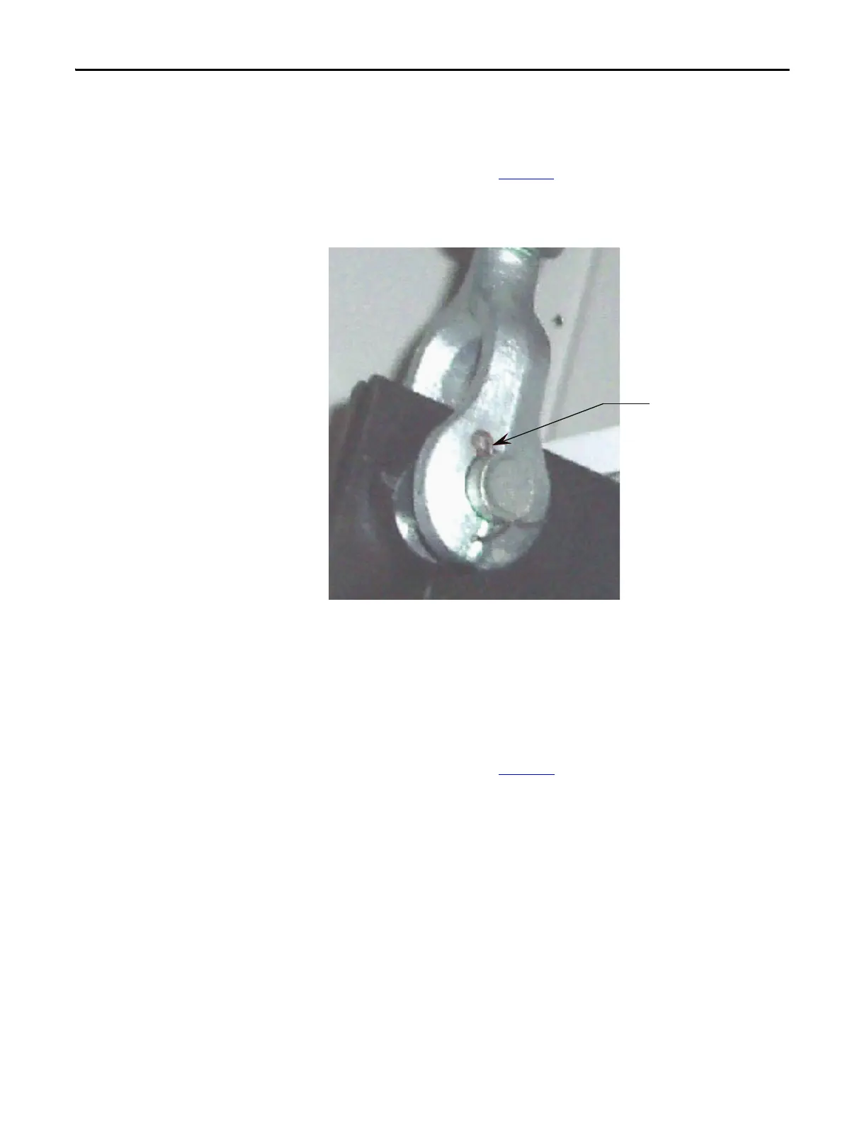
Remove turnbuckles which attach choke to top lifting angle pair as follows:
• Remove cotter pins (see Figure 43
) from bottom turnbuckle jaw then top.
Carefully remove turnbuckles. Retain for future use.
Figure 43 - Choke Cabinet
• Re-install any capacitors that were removed.
• Proceed with Removal of Lifting Angles.
Removal of Lifting Angles
Lifting angles should be removed only when the Drive is in its final location. The
lifting angles are retained with 5/8"-11 hardware. The 5/8" bolts need to be re-
installed in their holes in the top of the Drive to prevent the ingress of foreign
matter into the enclosures. See Figure 44
.

 Loading...


