326 Rockwell Automation Publication 7000L-UM301F-EN-P - March 2020
Chapter 5 Component Definition and Maintenance
Replacement Procedure
1. Ensure control power has been isolated and locked out.
2. Disconnect the terminals at the unit.
3. Remove the two M6 bolts per Figure 273
.
4. Extract the power supply complete with bracket from the drive.
5. Remove the bracket from the failed power supply (four M4 screws and
nylon shoulder washers).
6. Attach bracket to replacement power supply.
7. Repeat Steps 5, 4, 3, 2 and 1 in this order to replace the unit (see
Figure 273
).
8. Reapply control power and verify voltage levels.
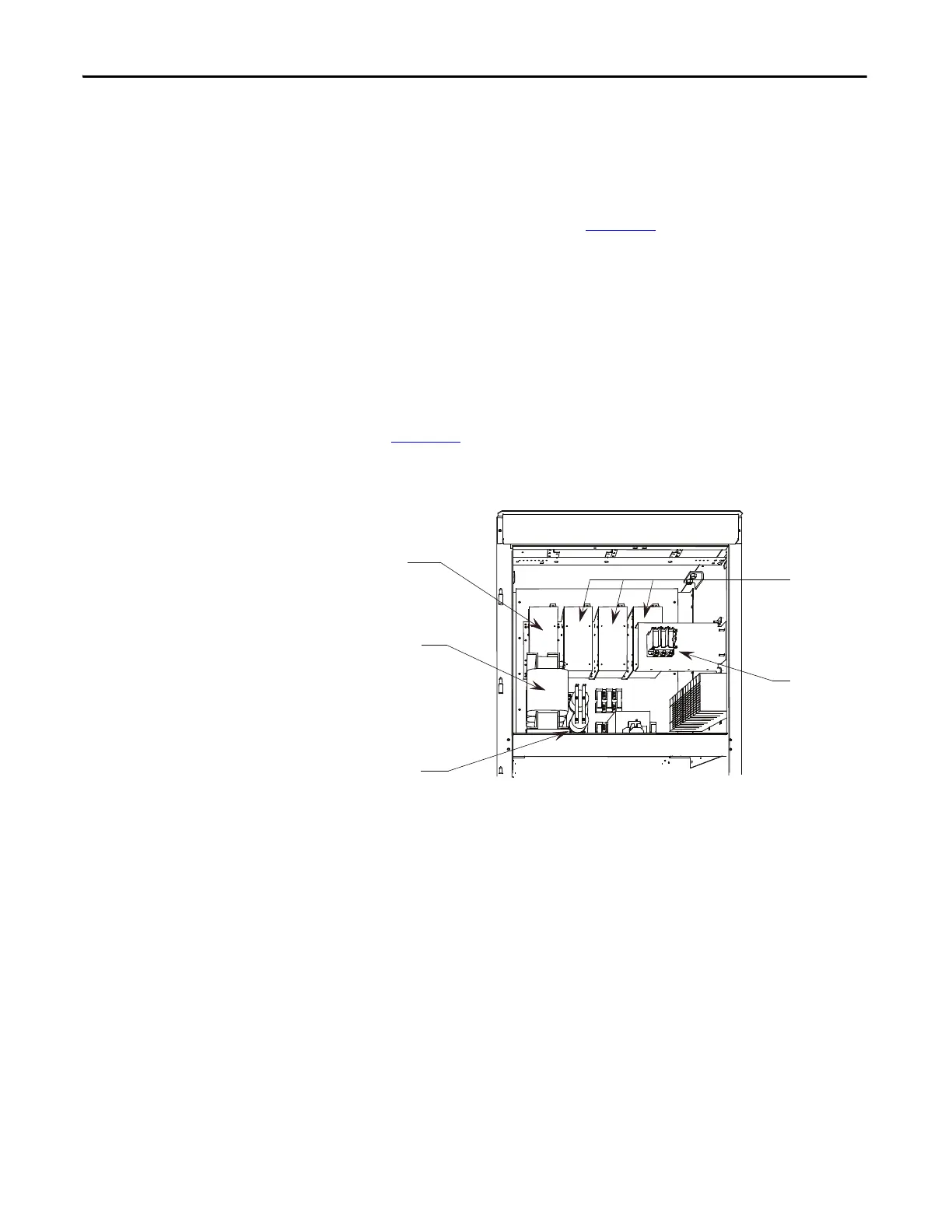
Figure 273 - Replacement of AC/DC Power Supply on Low Voltage Panel
Make sure the Black Insulation is between the AC/DC power supply and
the mounting plate.
Fuse Blocks
Power Supplies
(Optional)
AC/DC
Power Supply

 Loading...


