80 Rockwell Automation Publication 7000L-UM301F-EN-P - March 2020
Chapter 2 Drive Installation
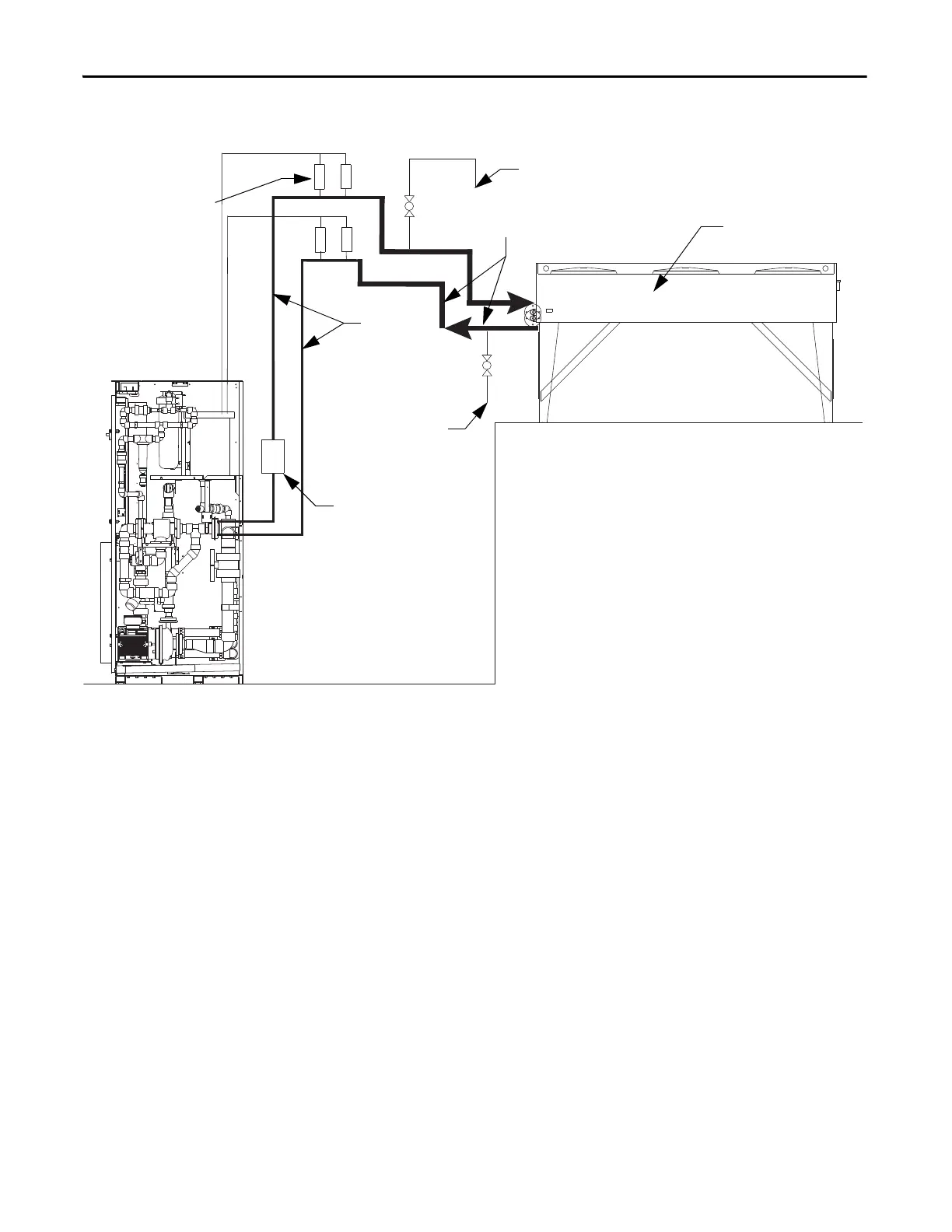
Figure 64 - Controlled Siphon Method with Elevated Heat Exchanger
Liquid-to-Liquid Heat
Exchangers
There are three options for routing piping between the liquid-to-liquid heat
exchanger to the supply and return coolant:
• Pipes through top plate of cabinet
• Pipes through bottom plate of cabinet
• Pipes through right side of cabinet
Removable plates are provided in each of these locations.
Drain
Fill
2 or 3 in.
piping
Ball Check
Valve
1.5 or 2 in.
piping
Vent Valve (x4)
ARV100VS Plastomatic
Mounting Notes:
• 2 ft max section of
horizontal piping for vent
valve mounting
• Horizontal vent valve piping
for exit and return must be
mounted at the same level
Heat Exchanger

 Loading...


