334 Rockwell Automation Publication 7000L-UM301F-EN-P - March 2020
Chapter 5 Component Definition and Maintenance
Piping, Tubing and Connectors
The piping is schedule 80 made from chlorinated polyvinyl chloride (CPVC)
which has good high and low temperature properties and is unaffected by de-
ionized water or ethylene glycol. The main piping is either 1.5 inch (38 mm) or
2.0 inch (50 mm) diameter.
The coolant hose connecting chill blocks to manifolds and Common Mode
Chokes or DC Links to piping is made of 10 mm (3/8") EPDM. The hose is
pushed onto hose barbs of stainless steel or CPVC. Hose clamps are used at the
hose barbs.
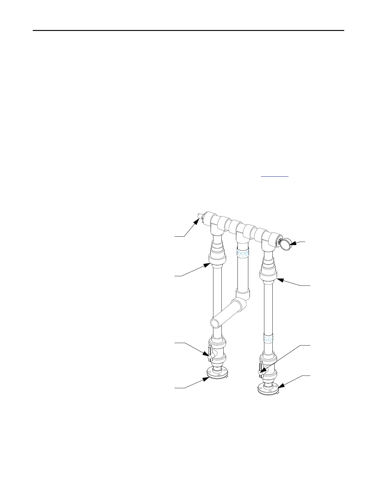
Non-Return Valves
The non-return valves (NV1 & NV2) shown in Figure 279 are ball-type valves
made from CPVC. These can not be changed with the drive on-line. All coolant
must be drained to replace these parts.
Figure 279 - Pressure Indicator and Switch Locations
Pressure Indicator PI
NV2
V12
From P2
From P1
V11
NV1
Pressure Switch PS

 Loading...


