86 Rockwell Automation Publication 7000L-UM301F-EN-P - March 2020
Chapter 2 Drive Installation
Information Regarding Termination of Customer Cables
Customer termination assemblies can accommodate either top or bottom
customer cable entry.
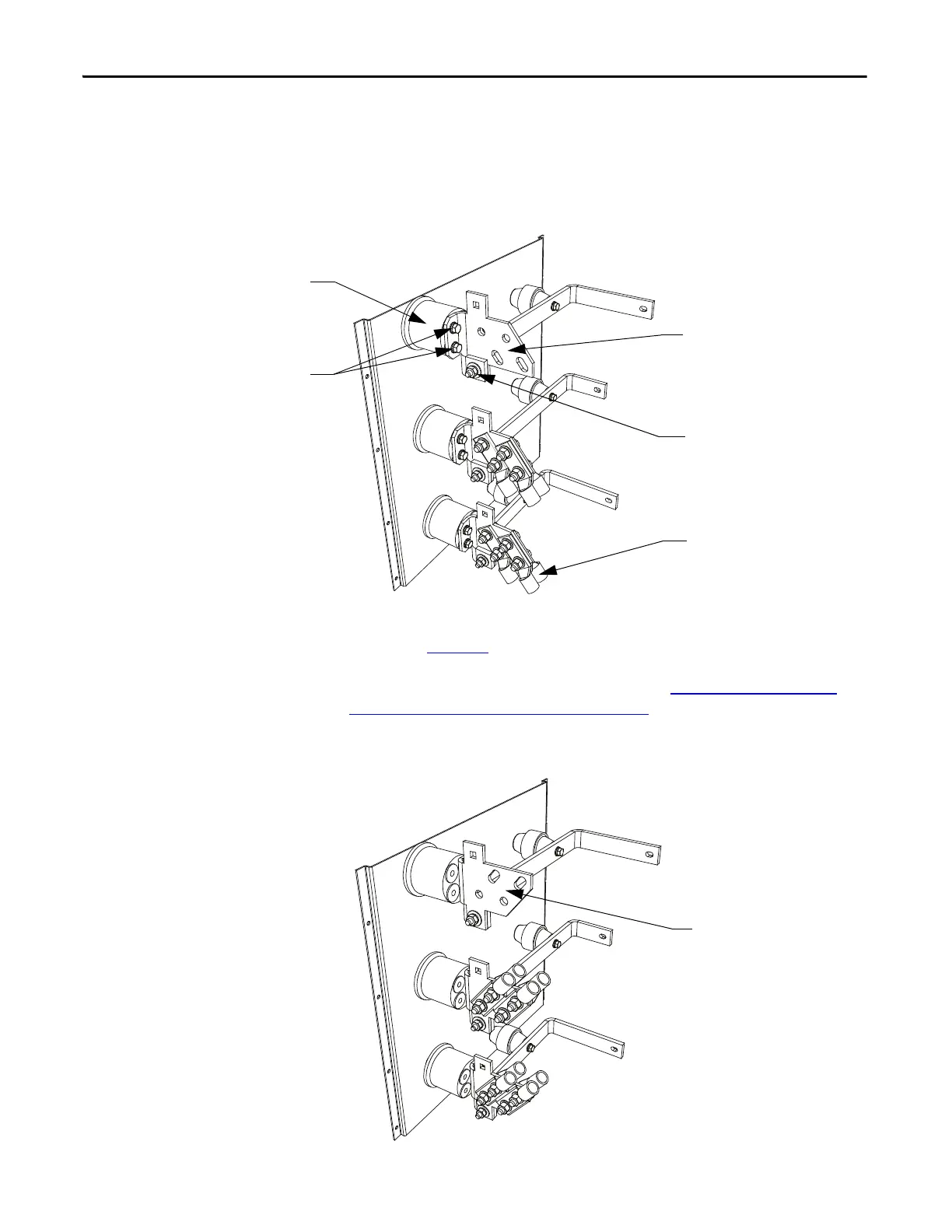
Figure 68 - Typical Line Cable Termination (shown assembled for bottom cable entry – 18 Pulse)
For top line cable entry, it is necessary to remove the lug pads and re-orient them
as shown in Figure 69
. To remove the lug pads, disconnect the M10 bus
connection hardware (17 mm hex tooling required). Remove the two bolts that
secure the lug pad to the 4-hole insulator. Refer to
Torque Requirements for
Threaded Fasteners on page 421 (Appendix B) for Torque Values of electrical
connections.
Figure 69 - Typical Line Cable Terminal Assembly (modified for top cable entry – 18 Pulse)
4-hole Insulator
Bolts
Lug pad shown with bottom
cable entry orientation
M10 bus
connection
hardware
Customer supplied lugs
4 lugs per phase maximum
Lug pad oriented for
top cable entry

 Loading...


