Rockwell Automation Publication 7000L-UM301F-EN-P - March 2020 261
Commissioning Chapter 4
Synchronous Transfer
When commissioning a drive employing synchronous transfer, the following
waveforms should be captured and submitted with the commissioning package.
Refer to the “Synchronous Transfer Commissioning Guidelines” for a detailed
commissioning procedure.
While measuring the bypass (BP) contactor closing time:
• Capture 120V bypass close command from the BP Contactor Close
output (J1-12) at the ACB (refer to electrical drawing for specific wire/
terminal number).
• Capture the 9V signal across the bypass contactor vacuum bottles (refer to
the tech note PowerFlex 7000_GEN-78 for details).
• Label the waveforms as “BP_Close_Cmd” and “Actual_Closure”.
• Save the worksheet as “Bypass Contactor Close Delay”.
Table 17 - Oscilloscope Setting
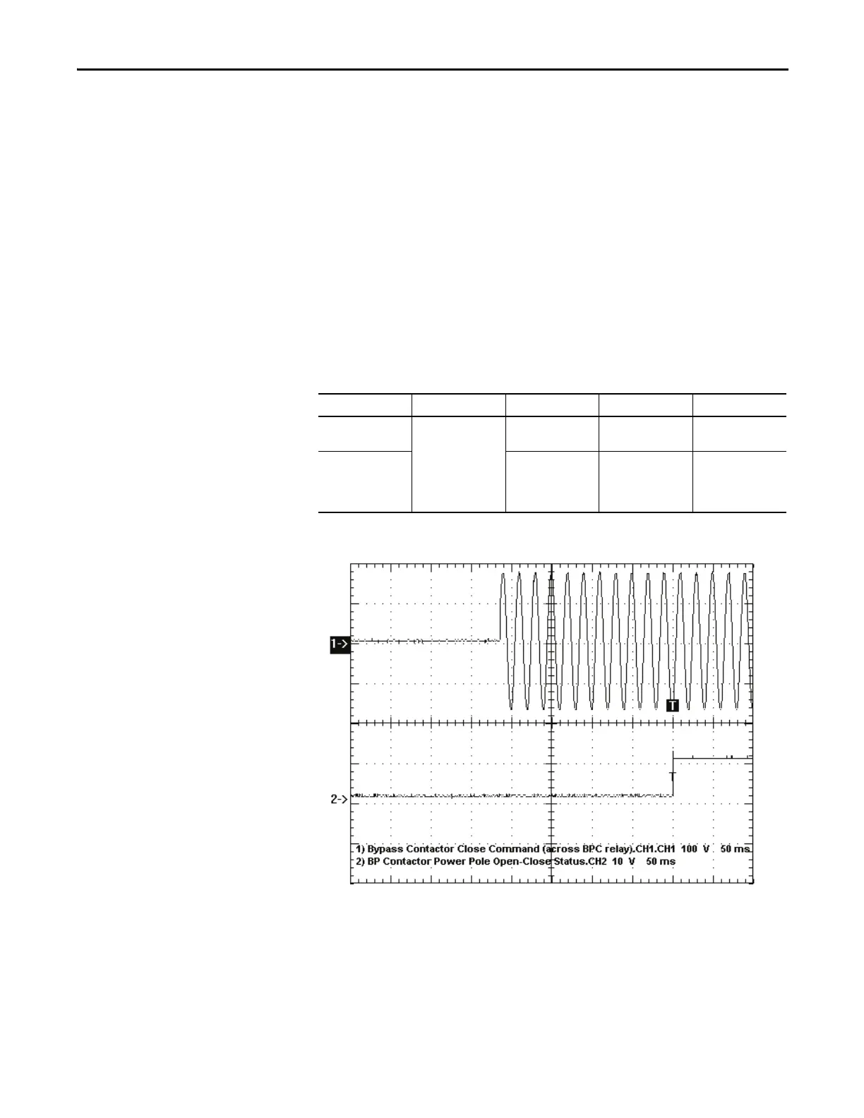
Figure 217 - Sample Waveforms
Ch1: Bypass Contactor Close Command (BPC output at ACB, J1-12 & 402)
Ch2: Actual Closure of Bypass Contactor (using 9V battery across contactor vacuum bottles)
While simulating a synchronous transfer to determine the best lead angle:
• Make sure the Diagnostic Trend has been setup and is armed.
• Capture motor voltage at ACB test point “Vu v ” & bypass voltage at ACB
test point “Vu v s ”.
Oscilloscope Time Base Waveform Test-Point Waveform Label
Ch. 1 25ms/div. BP Contactor Close
Command
BP Contactor Close
Cmd
BP_Close_Cmd
Ch. 2 Actual Closure of BP Across 2K-Ohm
resistor connected in
series with 9V
battery
Actual_Closure

 Loading...


