262 Rockwell Automation Publication 7000L-UM301F-EN-P - March 2020
Chapter 4 Commissioning
• Capture and trigger on falling edge of the DC Link current waveform at
ACB test point “Idc1”.
• Label the waveforms as “Vuv”, “Vuvs” and “Idc1”.
• Save the worksheet as “Drift @ 15 Degree Lead Angle”, for example.
Table 18 - Oscilloscope Setting
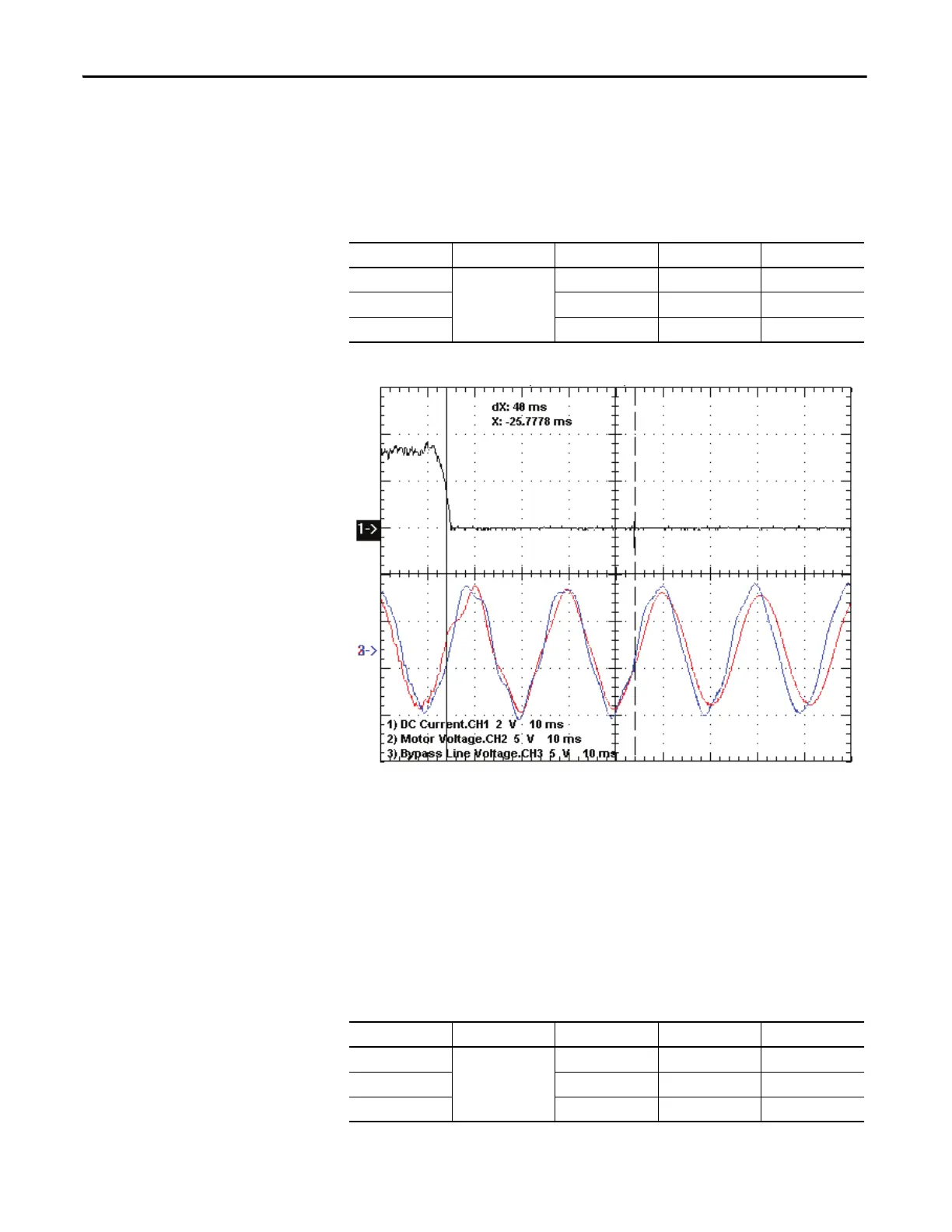
Figure 218 - Sample Waveforms
Synchronous Transfer Test to verify Sync Lead Angle (50Hz System)
Ch1: Idc1 (yellow), Ch2: Vuv (blue), Ch3: Vuvs (red)
While performing a live synchronous transfer:
• Capture motor voltage at ACB test point “Vu v ” & bypass voltage at ACB
test point “Vu v s ”.
• Capture and trigger on falling edge of the DC Link current waveform at
ACB test point “Idc1”.
• Label the waveforms as “Vuv”, “Vuvs” and “Idc1”.
• Save the worksheet as “Synch on Motor 01”, for example.
Table 19 - Oscilloscope Setting
Oscilloscope Time Base Waveform Test-Point Waveform Label
Ch. 1 10ms/div. DC Link Current Idc1 Idc1
Ch. 2 Motor Voltage Vuv Vuv
Ch. 3 Bypass Line Voltage Vuvs Vuvs
Oscilloscope Time Base Waveform Test-Point Waveform Label
Ch. 1 10ms/div. DC Link Current Idc1 Idc1
Ch. 2 Motor Voltage Vuv Vuv
Ch. 3 Bypass Line Voltage Vuvs Vuvs

 Loading...


