240 Rockwell Automation Publication 7000L-UM301F-EN-P - March 2020
Chapter 4 Commissioning
T DC Link High - indicates that the measured dc link time constant is greater
than 0.150 second. The step response of the current regulator should be checked
using the manual method described below.
Input Impedance Manual Tuning
1. Set parameter Operating Mode in Feature Select to DC Current to enter dc
current test mode.
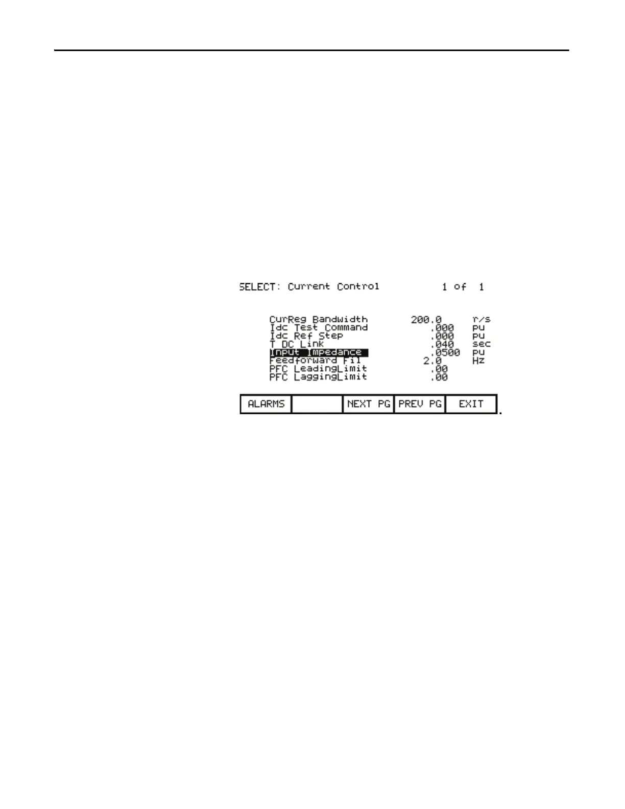
2. If not already at default value, set parameter Input Impedance in “Current
Control” to an initial value of 0.05 pu.
Figure 207 - Current Control Parameter Screen
3. Energize the drive by closing the input contactor.
4. Record the value of the rectifier input voltage by looking at parameter Rec
Input Voltage (P696). Let this value be V
in0
.
5. For SCR drives set parameter Idc Command Test in Current Control to
0.800 pu. For AFE drives set the parameter to 0.300 pu. Let this value be
I
dc
.
6. Start the drive and wait for a few seconds for steady state conditions to be
established.
7. Record the value of the rectifier input voltage by looking at parameter Rec
Input Voltage (P696). Let this value be V
in1
.
8. The value of input impedance for AFE drives is calculated as follows:
C
in
is the value of input filter capacitor given by Line Filter Cap (P133)
9. The value of input impedance for SCR drives is calculated as follows:
The display screens are given as an example. The actual screen data
may differ.
This section is not applicable to ForGe.
L
in
V
in0
V
in1
–
I
dc
C+
in
V
in0
V–
in1
()
----------------------------------------------------
= for PWM drives

 Loading...


