Rockwell Automation Publication 7000L-UM301F-EN-P - March 2020 319
Component Definition and Maintenance Chapter 5
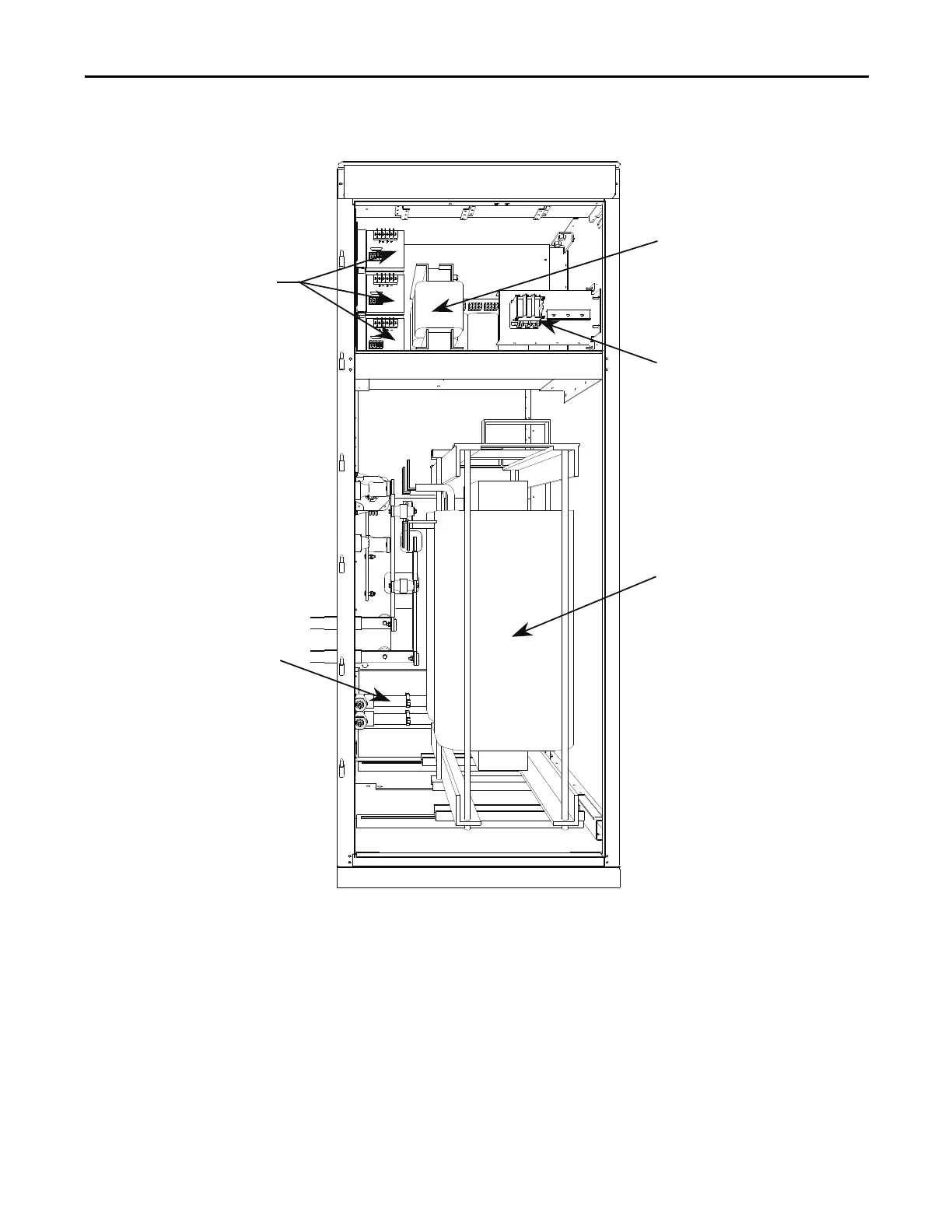
Figure 266 - DC Link and Control Power Cabinet
The door of the Control Power Panel is interlocked so that it cannot be opened
unless the 3-phase control power is disconnected. When the door is opened, the
AC Control Power transformer and the AC/DC power supplies are accessible.
This is the section where the customer 3-phase power is brought into the drive.
The DC Link is mounted on the floor beneath the control power section. The
larger door is interlocked with the rest of the system and cannot be opened unless
the MV power is locked-out. The DC Link is part of the cooling circuit for the
PowerFlex 7000L “C” Frame drive, and has 2 inlets and 2 outlets for coolant flow.
AC/DC
Power Supplies
Fuse Blocks
Power Transformer
Liquid-Cooled
DC Link Reactor
Cooling Pipes
 Loading...


