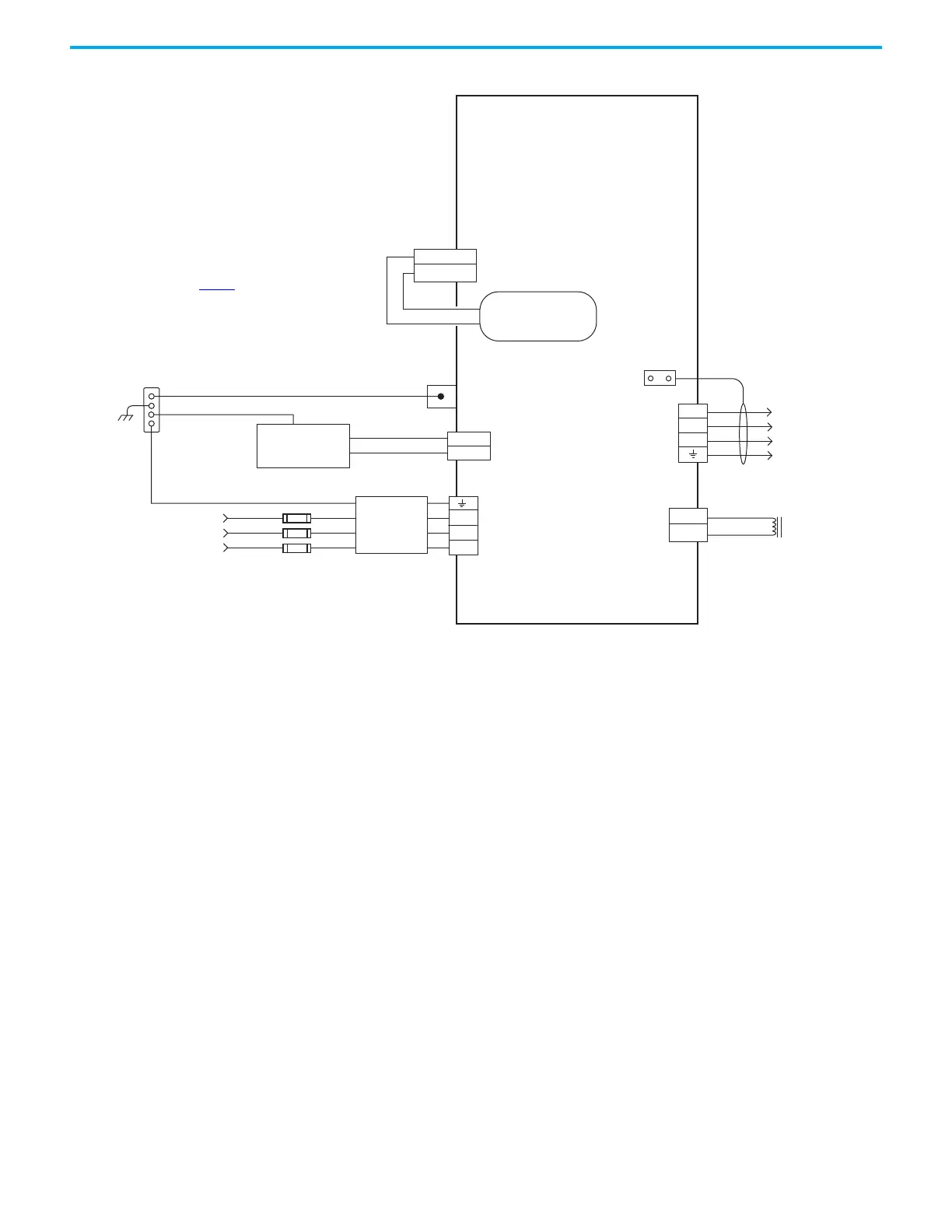
EasyManuals Logo

Rockwell Automation Allen-Bradley Ultra3000 User Manual

Rockwell Automation Allen-Bradley Ultra3000
80 pages
To Next Page IconTo Next Page
To Previous Page IconTo Previous Page
Page #72 background imageLoading...
Page #72 background image
74 Rockwell Automation Publication 2198-RM006A-EN-P - December 2020
Appendix D Interconnect Diagrams
Figure 25 - Kinetix 5300 Drives Power Wiring (three-phase operation)
L3
L2
L1
24V_COM
+24V
2
1
MBRK -
MBRK +
4
3
2
1
MBRK -
MBRK +
U
V
W
2
1
4
3
2
1
DC+
SH
170…253V AC rms or
342…528V AC rms
Three-phase Input
Note 1
Bonded Cabinet Ground Bus
Control Power
Connector
PE Ground
Note 6
Mains AC Input
Connector
Circuit Protection *
Note 2
* Indicates User Supplied Component
2198-C1004-ERS, 2198-C1007-ERS,
2198-C1015-ERS, 2198-C1020-ERS,
2198-C2030-ERS, 2198-C2055-ERS,
2198-C2075-ERS, 2198-C4004-ERS,
2198-C4007-ERS, 2198-C4015-ERS,
2198-C4020-ERS, 2198-C4030-ERS,
2198-C4055-ERS, 2198-C4075-ERS
Kinetix 5300 Drives
Chassis
Note 4
Customer Supplied
+24V DC
Power Supply *
Motor Brake
Connector
Three-phase
Motor Power
Connections
Note 8
Motor Power
Connector
Cable Shield
Clamp
Note 5
See Table 53
for note information.
Shunt
Connector
Motor Brake
Connections
2198-DBxxx-F
Three-phase
AC Line Filter
Note 3
Internal Shunt
Note 7

Table of Contents

Other manuals for Rockwell Automation Allen-Bradley Ultra3000

Questions and Answers:

Question and Answer IconNeed help?

Do you have a question about the Rockwell Automation Allen-Bradley Ultra3000 and is the answer not in the manual?

Rockwell Automation Allen-Bradley Ultra3000 Specifications

General IconGeneral
BrandRockwell Automation
ModelAllen-Bradley Ultra3000
CategoryServo Drives
LanguageEnglish

Related product manuals