3-4
Document: 553632
(ICSTT-RM448_EN_P) Issue: 08:
System Build Manual (AADvance Controller)
Allocations of Coding Pegs
Allocations of Coding PegsAllocations of Coding Pegs
Allocations of Coding Pegs
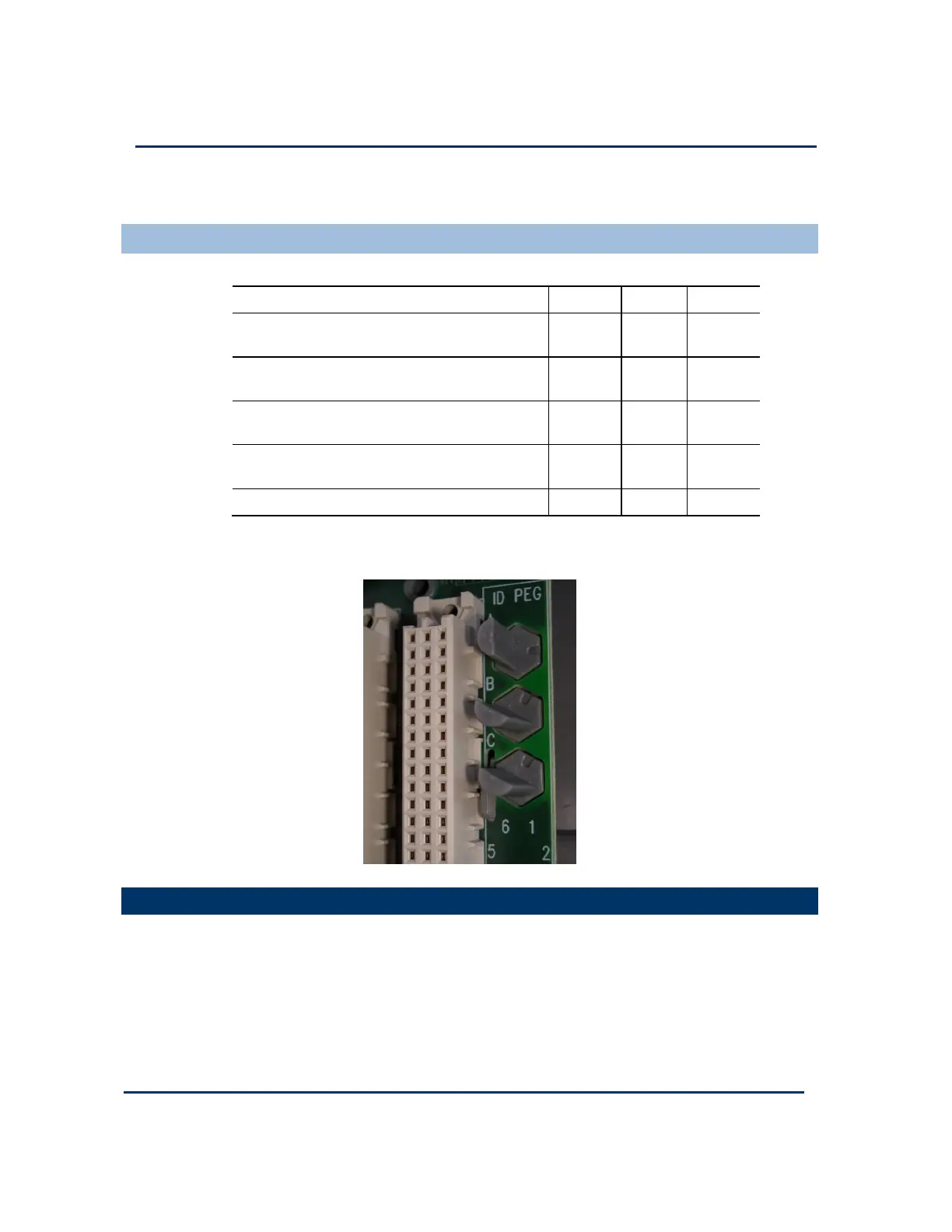
Coding pegs are assigned to each module type as shown in the following table:
Application Key A Key B Key C
9100 processor base unit
(for 9110 processor module)
1 1 1
9801/2/3 digital input termination assemblies
(for digital input modules)
2 1 1
9831/2/3 analogue input termination assemblies
(for analogue input modules)
2 1 3
9851/2 digital output termination assemblies
(for digital output modules)
3 1 1
9842/1 analogue output module 3 1 2
This example shows pins set to positions 2, 1, 1 for a 9401 digital input module.
Install Base Units and Ter
Install Base Units and TerInstall Base Units and Ter
Install Base Units and Termination Assemblies: Flat Panel Assembly
mination Assemblies: Flat Panel Assemblymination Assemblies: Flat Panel Assembly
mination Assemblies: Flat Panel Assembly
Flat panel assembly secures the AADvance controller directly onto a panel, without
the use of DIN rails. Do the following:
1) The base units carry latches which are intended to secure the base units to DIN
rails.
2) Assemble the base units. Place the base units on a workbench and use the
backplane clips (supplied) to join adjacent base units together.
 Loading...