3-10
Document: 553632
(ICSTT-RM448_EN_P) Issue: 08:
System Build Manual (AADvance Controller)
Procedu
ProceduProcedu
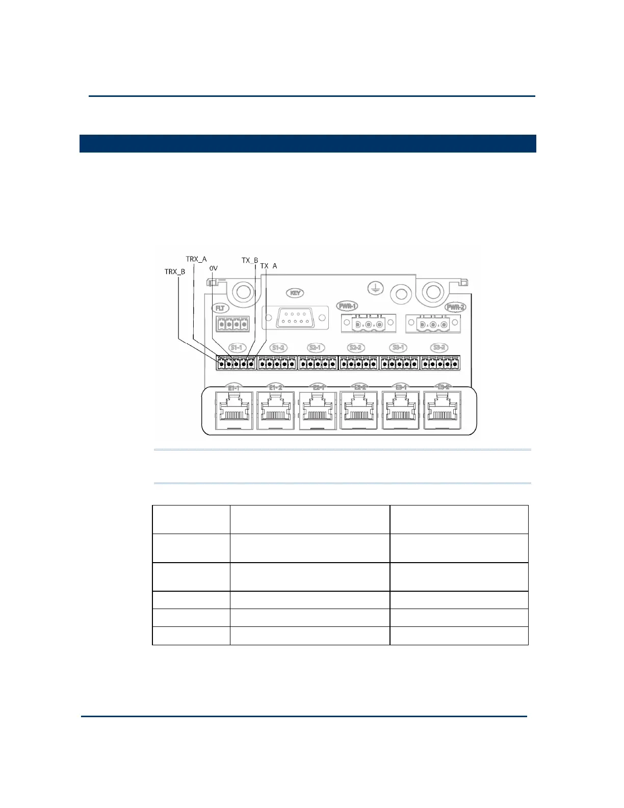
Procedure to Connect Serial Communications Cabling
re to Connect Serial Communications Cablingre to Connect Serial Communications Cabling
re to Connect Serial Communications Cabling
Connect the serial communications cabling to the six plugs labelled S1-1 through S3-2
on the T9100 processor base unit.
For each serial communications connection, connect the cabling according to the
following illustration.
Apply a minimum tightening torque of 0.22Nm (0.16ft lb) to the terminal screws.
Make sure the length of the cable does not exceed 1,200m (3,900ft).
Note: The line functions shown in this table ("receive" and "transmit") are with
respect to the processor base unit.
Terminal Function Description (4-wire) Function Description (2-
wire)
TRX_A Receive data A (inverting) Transmit/receive data A
(inverting)
TRX_B Receive data B (non-inverting) Transmit/receive data B (non-
inverting)
0V Instrument ground (signal ground) Instrument ground
TX_B Transmit data B (non-inverting) not used
TX_A Transmit data A (inverting) not used
To connect to the external communication link you should terminate the receive end
of the link.

 Loading...


