Document: 553632
(ICSTT-RM448_EN_P) Issue: 08:
4-7
Step Task
When the Run indicator goes AMBER press the Fault Reset button and the processor will display the
following indications:
2. Healthy Green
Ready GREEN (can flash for a short time as the module educates)
Run AMBER to GREEN (AMBER as the module educates)
System Healthy GREEN
Force Off to GREEN
Aux Off (application dependent)
Serial 1 Dependent on Data Connection
Serial 2 Dependent on Data Connection
Ethernet 1 Dependent on Data Connection
Ethernet 2 Dependent on Data Connection
3. To insert a 3rd processor module repeat step 1 and insert in Slot C.
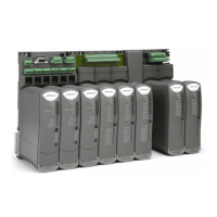
I/O Module Start Up Process
I/O Module Start Up ProcessI/O Module Start Up Process
I/O Module Start Up Process
To start up an Input/Output Module follow this procedure:
Note: The start up sequence is different when a module is installed into an on-line
system that is running compared to installing the module into a system that is off-line
and has processor modules but no I/O modules installed. The first part of this
procedure covers the initial start up of an off-line system, the second part covers a
system that is on line and you are adding I/O modules.
Table 10:
Table 10: Table 10:
Table 10: Single
Single Single
Single Module or First Module of a group Installation Procedure
Module or First Module of a group Installation ProcedureModule or First Module of a group Installation Procedure
Module or First Module of a group Installation Procedure
Step Task
1. This procedure applies to a single module installed or the first module of a redundant group.
2 Install the Input/Output Module and turn the locking screw to the lock position.
3. The input module will provide the following status indications:
Healthy GREEN
Ready RED
Run RED
Channel 1 – 8 Off
4. The input module will enter its start up sequence during which the module will educate.
Wait for approximately 3 seconds.
5. The module will now provide the following status indications:
Healthy GREEN
 Loading...


