3-68 Programming and Parameters
PowerFlex Digital DC Drive User Manual - Publication 20P-UM001C-EN-P - July 2008
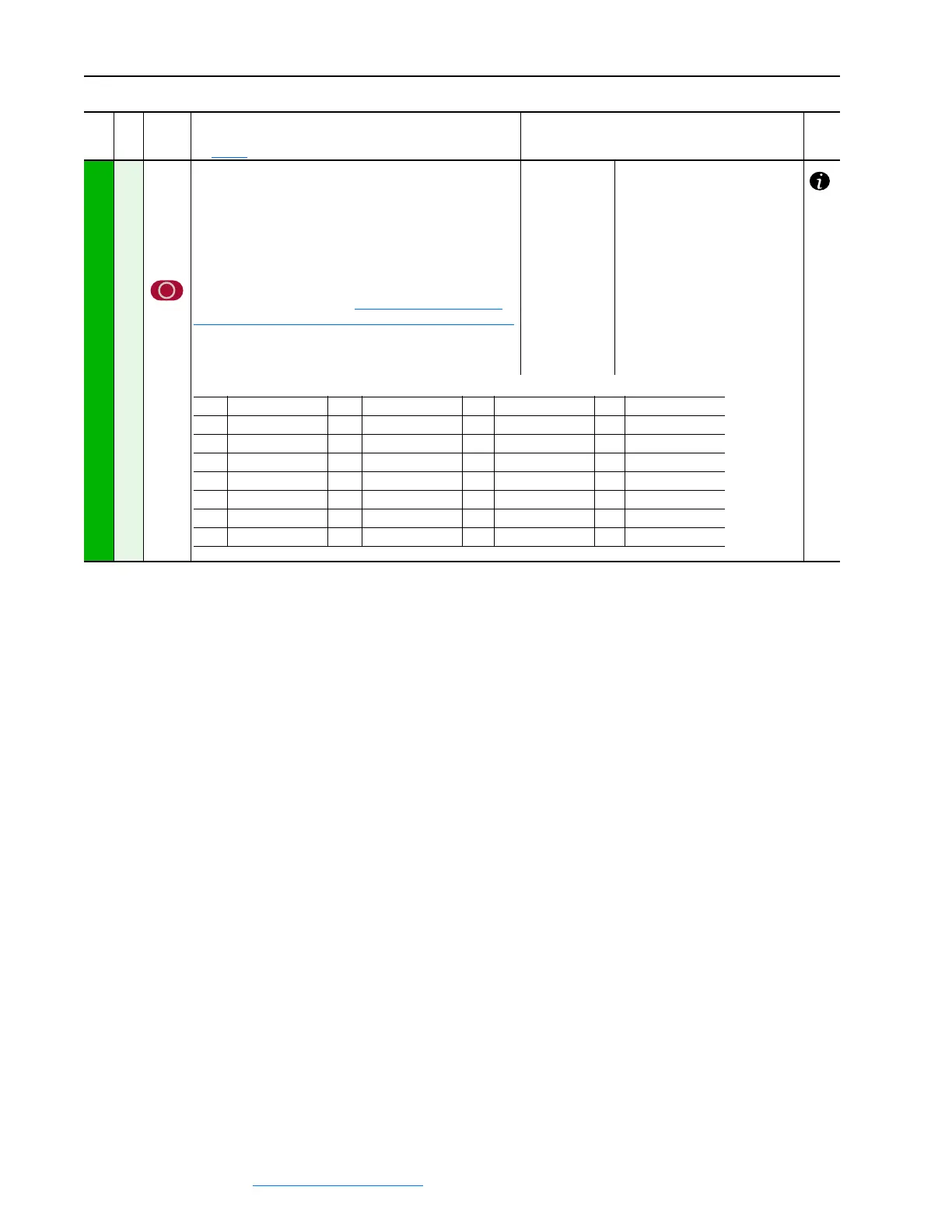
INPUT / OUTPUT
Digital Outputs
145
146
147
148
149
150
151
152
[Digital Out1 Sel]
[Digital Out2 Sel]
[Digital Out3 Sel]
[Digital Out4 Sel]
[Digital Out5 Sel]*
[Digital Out6 Sel]*
[Digital Out7 Sel]*
[Digital Out8 Sel]*
Selects the source of the value that drives the digital output.
Refer to “Option Definitions” on Option Definitions for [Digital
Outx Sel], [Relay Out 1 Sel] and [Relay Out 2 Sel] on page 3-69.
*These parameters are used to configure the digital outputs on
the I/O Expansion circuit board.
Options:
Default:
Default:
Default:
Default:
Default:
Default:
Default:
Default:
5 =
9 =
2 =
4 =
26 =
0 =
0 =
0 =
“Ready”
“Fault”
“Spd Thresh”
“CurrentLimit”
“Alarm”
“Not Used”
“Not Used”
“Not Used”
File
Group
No.
Parameter Name & Description
See page 3-2 for symbol descriptions
Values
Related
0 = “Not Used” 8 = “Spd Limited” 16 = “Encoder Err” 24 = “Reserved”
1 = “Spd Zero Thr” 9 = “Fault” 17 = “Diam Calc” 25 = “Reserved”
2 = “Spd Thresh” 10 = “Power Loss” 18 = “Input1 Cmp” 26 = “Alarm”
3 = “At Speed” 11 = “UserDefinedA” 19 = “Diam Reached” 27 = “Running”
4 = “CurrentLimit” 12 = “UserDefinedB” 20 = “Speed Match” 28 = “Jogging”
5 = “Ready” 13 = “Stop Control” 21 = “Accelerating” 29 = “Active”
6 = “Ramp Pos” 14 = “Field Loss” 22 = “Decelerating”
7 = “Ramp Neg” 15 = “Spd Fbk Loss” 23 = “Brake Cmd”
 Loading...


