EVISION - HD101 & HD102 www.roevisual.com
V1.13, 2020-05-20 | Copyright © 2020 ROE Visual Co., Ltd. All Rights Reserved.
15 / 41
5 Quick Start Guide
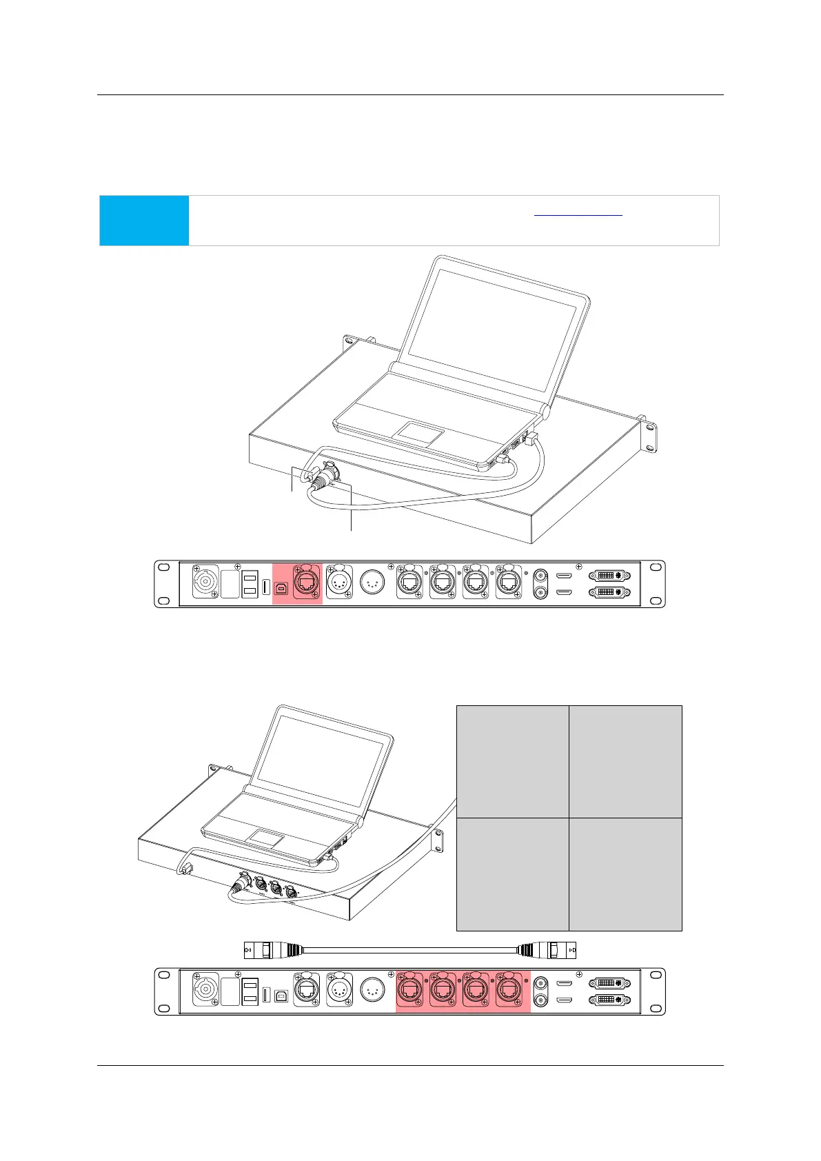
5.1 PC-Processor Control Signal Cabling
Connect the processor with the PC, using ether USB cables (USB type A, male – type B, male) or Ethernet
cables (fast Ethernet).
NOTICE
If using Ethernet cable for control, please refer to page 39, 9.3 IP Setup before further
steps.
Figure 5-1. PC to processor connection
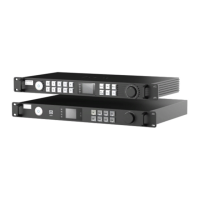
5.2 Processor Output Cabling
Connect the processor with the LED tiles, using Gigabit Ethernet cables (Cat5e or Cat6).
Figure 5-2. Processor to LED connection
HD MI IN
USB
OUT
P OR T1
PO RT2
P ORT3
P OR T4
INPUT 100-240V A C 50/60 Hz
DV I IN
DVI L OOPHD M I LO OP
RE F IN
RE F OUT
DMX I N
DMX OUT
NE T
USB
IN
FIBER 2
F IBE R1
Ethernet C ab le RJ4 5-R J45 (up to 100m )
USB Cable A ma le- B male (up to 3m )
HD MI IN
USB
OUT
P OR T1 P ORT2 P ORT3 P OR T4INPUT 100-240V A C 50/60 Hz
DVI IN
DVI L OOPHDM I LO OP
RE F IN
RE F OUT
DMX I NDMX OUTNE T
USB
IN
FIB ER2
F IBE R1
LED Wall