W
wclarkAug 1, 2025
How to prevent risk of damage to boards in Rohde & Schwarz Inverter?
- SsteelecurtisAug 1, 2025
To prevent damage to the boards, exercise caution to avoid short circuits when measuring voltages at closely spaced pins.
How to prevent risk of damage to boards in Rohde & Schwarz Inverter?
To prevent damage to the boards, exercise caution to avoid short circuits when measuring voltages at closely spaced pins.
What to do if there is a shock hazard with Rohde & Schwarz Inverter?
To avoid a shock hazard, ensure the instrument is switched off and completely disconnected from the power supply by unplugging it from both the AC and DC power connectors.
Describes safety symbols and their meanings on product labels.
Explains the meaning of signal words like DANGER, WARNING, CAUTION, NOTICE.
Specifies conditions and positions for safe product operation.
Details safety precautions for electrical connections and operation.
General instructions for safe and proper product operation.
Guidelines for safe handling, storage, and disposal of batteries.
Safety instructions for moving and transporting the product.
Information on proper disposal of product components and waste.
Information required and precautions for shipping the instrument for service.
Guidelines for packaging and shipping defective modules.
Information needed to order spare parts correctly and promptly.
Information on economical alternatives to original modules.
Procedure for returning defective replacement modules for credit.
Steps for testing R&S SMB function and compliance with specifications.
Lists necessary equipment and accessories for performance tests.
Steps to ensure proper conditions for performance tests and prevent errors.
Detailed procedures for verifying instrument parameters.
Procedures for checking internal and external reference frequency accuracy.
Procedure for checking frequency setting by internal synthesizer adjustments.
Procedure for measuring the time taken for frequency to settle within tolerance.
Procedures for measuring harmonics and nonharmonics.
Procedures for measuring nonharmonic suppression values.
Procedure for measuring non-systematic nonharmonics.
Procedure for measuring wideband noise and calculating broadband noise floor.
Procedures for measuring Single Sideband (SSB) phase noise.
Procedure for measuring residual frequency modulation.
Procedure for measuring residual amplitude modulation.
Procedures for measuring level uncertainty and power meter levels.
Procedure for measuring output impedance using VSWR.
Procedures for checking frequency accuracy, distortions, and level accuracy.
Procedures for measuring AM setting uncertainty and distortion.
Procedures for setting up and measuring FM deviation and distortion.
Procedures for measuring ON/OFF ratio, rise/fall time, and video crosstalk.
Procedures for measuring frequency response, distortion, and channel separation.
Procedure for measuring signal-to-noise ratio for stereo signals.
Procedures for measuring MPX, pilot tone, and RDS subcarrier deviation.
Procedure for checking preemphasis settings for FM stereo signals.
Procedure for testing digital audio signal path using S/P DIF.
Procedure for testing RDS data transmission and decoding.
Procedure for testing the SIGNAL VALID hardware signal.
Steps for setting date/time after lithium battery replacement.
Steps for installing new firmware after basis board replacement.
General remarks on performing adjustments after module replacement.
Information on accessing internal adjustments via the setup menu.
How to perform all internal adjustments for the complete unit.
Information on external adjustments needing calibrated equipment.
Procedure for measuring and correcting output power over frequency and level.
Procedure for adjusting the internal reference frequency accuracy.
Procedures for adjusting analog and digital audio signal paths.
Recommended procedure to check instrument operation after module replacement.
Overview of the signal generator's design and module functions.
Details on the RF board's functions, components, and design.
Description of the power supply module's operation and specifications.
Components and modules included on the basis board.
Instructions for tracing down malfunctions to the board level.
Lists equipment needed for troubleshooting procedures.
Analysis of issues related to powering on the instrument.
Troubleshooting steps for when the unit fails to start the application.
Utility to check the operation of front panel control elements.
Using the internal selftest to diagnose module failures.
Troubleshooting for issues related to internal adjustments.
Lists common faults and tests to identify defective modules.
Specific troubleshooting steps for the basis board module.
Troubleshooting steps for assumed errors on the RF board module.
Troubleshooting for the reference oscillator option.
Troubleshooting for the stereo/RDS coder option.
Information on updating the instrument's firmware via USB.
Guidance on installing hardware and software options.
Information on installing and replacing hardware options.
Information on enabling software options using key codes.
List of spare parts and stock numbers for ordering.
List of available power cables with their specifications.
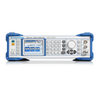
| Brand | Rohde & Schwarz |
|---|---|
| Model | SMB100A |
| Category | Inverter |
| Language | English |