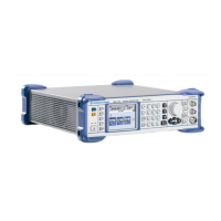
Module Replacement R&S SMB
1407.0806.82 3.38 E-6
Module Replacement
This section describes in detail the replacement of modules. Chapter 5 provides information on how to
order spare parts; it contains the list of mechanical parts with order numbers and the illustrations for
module replacement.
Overview of the Modules
Table 3-1 Overview - module replacement
Module
Designation
Instrument
Part No.
Replacement Part
Order No.
See page
Power Supply (AC 90 V to 264 V)
A50 1406.7320.00
1406.7336.00
1406.7336.00
3.54
Basis Board
A100
1406.6600.02
1406.6700.02
1406.6700.02
3.47
1406.7007.03
1406.7007.13
1406.7207.03
1406.7207.13
1406.7220.03
1406.7220.13
1407.7800.03
1407.7800.13
See spareparts list
1406.6030.01 ST in
chapter 5.
RF Board
A200
1406.7007.06
1406.7007.16
1406.7207.06
1406.7207.16
1406.7220.06
1406.7220.16
1407.7800.06
1407.7800.16
See spareparts list
1406.6030.01 ST in
chapter 5.
3.52
Reference Oscillator OCXO R&S SMB-B1
A210
1300.3180.03
1300.3180.03
3.57
Stereo Coder R&S SMB-B5
A400 1407.3240.00 1407.3240.00
3.58
1406.7507.02
1406.7507.02
Front Unit R&S SMB100A A300
1406.7807.02 1406.7807.02
3.40
Encoder Board
A310 1300.3044.02 1300.3044.02
3.45
1407.3586.00 1407.3586.00
3.5" TFT (QVGA DRGB LCD)
A330
3585.1400.00 3585.1400.00
3.44
Push Button Board Set or
Flex. Switch Board
1406.7542.00
1406.7559.00
1406.7542.00
1406.7559.00
3.45
Front Cover
1406.7520.00 1406.7520.00
3.40
Fan Unit
E1
1406.6330.00
1406.6330.00
3.56
Lithium battery CR 2477N (3.0 V / 0.95 AH)
4052.5673.00 4052.5673.00
3.49
Notes: All modules can be replaced with modules with the same part number or with replacement
modules as listed above.
The words "left" and "right" in the manual always refer to the front view of the instrument.
After replacing an assembly
After you have replaced one of the assemblies, certain adjustments, functional checks or performance
tests have to be carried out. Please refer to chapter 2 “Procedures after module replacement”.

 Loading...