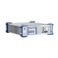
R&S SMB Instrument Design and Function Description
1407.0806.82 3.1 E-6
3 Repair
Instrument Design and Function Description
A schematic of the signal generator's design is presented below as block diagram at module level
The R&S SMB consists of very few main modules and very few connections between these modules. The
main units are:
• Power Supply
• Basis Board which includes all digital external Interfaces, the main CPU, the Fan control logic, the
hardware drivers for the front panel and the Interface for the RF Board.
• Front Unit consisting of the rotary knob with encoder, the flexible switch board and the QVGA
Color Display
• RF Board including the whole measurement hardware.
• R&S SMB-B1 Reference Oscillator which is plugged direct into the RF Board.
• R&S SMB-B5 Stereo/RDS Coder with ribbon cable for connection to the Basis Board and
shielded cables for connection to the rear panel.
A detailed description of these modules is given in the next chapter.

 Loading...