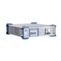
Contents – Repair R&S SMB
1407.0806.82 I-3.2 E-6
Troubleshooting @ Reference Oscillator option R&S SMB-B1...............................................3.30
I
nput and Output Signals .............................................................................................3.30
Error Messages Concerning the Reference Oscillator Module ...................................3.31
Frequency Error,
Reference Oscillator Adjustment .....................................................3.31
Troubleshooting @ Stereo/RDS Coder option R&S SMB-B5 .................................................3.32
Input and Output Signals .............................................................................................3.32
Error Messages concerning the Stereo/RDS Coder module.......................................3.34
Stereo/RDS Coder adjustment ....................................................................................3.35
Stereo/RDS Coder Faults ............................................................................................3.35
Stereo/RDS Coder signal path check ..........................................................................3.36
Module Replacement .....................................................................................................................3.38
Overview of the Modules........................................................................................................3.38
After replacing an assembly...................................................................................................3.38
Dismounting the Case............................................................................................................3.39
Replacing Fuses ....................................................................................................................3.39
Replacing the Front Cover and the Front Unit (A300) ...........................................................3.40
Removing the Front Cover...........................................................................................3.40
Removing the Front Unit ..............................................................................................3.40
Mounting the Front Unit ...............................................................................................3.43
Mounting the Front Cover ............................................................................................3.43
Replacing the TFT Display (A330), Encoder Board (A310), Flex. Switch Board
and Pushbutton Board Set...........................................................................................3.44
Replacing the Encoder Board......................................................................................3.45
Replacing the TFT Display, Flex. Switch Board and Pushbutton Board Set...............3.45
Replacing the Basis Board (A100) .........................................................................................3.47
Removing the Basis Board ..........................................................................................3.47
Installing the Basis Board ............................................................................................3.48
Replacing the Battery (G1)
..........................................................................................3.49
Replacing the SIM Card
...............................................................................................3.50
Replacing the RF-Board (A200).............................................................................................3.52
Removing the RF-Board ..............................................................................................3.52
Installing the RF-Board ................................................................................................3.53
Replacing the Power Supply (A50) ........................................................................................3.54
Removing the Power Supply .......................................................................................3.54
Installing the Power Supply .........................................................................................3.55
Replacing the Fan Unit (E1)...................................................................................................3.56
Replacing the Reference Oscillator Option R&S SMB-B1 (A210) .........................................3.57
Replacing the Stereo/RDS-Coder Option R&S SMB-B5 (A400) ...........................................3.58
Removing the Stereo/RDS-Coder ...............................................................................3.58
Installing the Stereo/RDS-Coder .................................................................................3.59

 Loading...