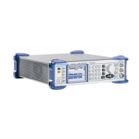
R&S SMB Procedures after Module Replacement
1407.0806.82 2.3 E-5
External Level Correction
External level correction measures output power over frequency and level and stores the correction
values inside the instrument to maintain level accuracy. The R&S SMB provides a build in measuring
procedure for external level correction.
NOTICE
R
isk of damage to the power sensor
Power sensor NRP-Z91 can be damaged when being exposed to R&S SMBs
maximum output power. So it is recommendet to PRESET the instrument
before connecting the power sensor. The build-in level correction procedure
does not overload the sensor.
Adjustment
Test equipment
R&S NRP-Z91 or R&S NRP-Z92 power sensor with NRP-Z3 or
NRP-Z4 USB adaptor
Test setup
Power on instrument
Setting on instrument:
PRESET
Setup Menu
Reference Oscillator
Source INTERNAL
Protection
Protection Level 2 = 147946 ENTER
Connect the power sensor to the RF plug and to the USB
connector of the instrument.
Allow the R&S SMB and the power sensor to warm up for at least
20 minutes
Adjustment Setting on instrument:
Setup Menu
Internal Adjustments
Adjust Ext Level…
ECEXUTE
Adjustment Data CUSTOM
Note that the R&S factory level correction data is not replaced
by this procedure, instead an additional data set is created.
The active correction data set is selected by the setting
“Adjustment data”

 Loading...