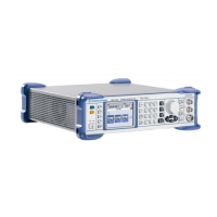
Instrument Design and Function Description R&S SMB
1407.0806.82 3.2 E-6
RF Board
The RF BOARD contains the complete measuring hardware of the instrument. The RF and LF signals are
generated and modulated on the module. The output level is controlled by a level control loop controlling
the level before the step attenuator. The fully electronic step attenuator is temperature compensated to
achieve very precise output levelling of the instrument. The RF Board is equipped with a reverse power
protection to ensure the instrument not being damaged due to supplying reverse power to the RF output
of the instrument. The module is controlled by the Basis Board via a serial bus and few additional control
signals.
Implemented functions
• Reference crystal oscillator and reference frequency switch
• Synthesizer
• LF generator
• Pulse generator and Pulse modulator control
• Modulation matrix
• DDS module including AM/FM/ 2M modulator
• AM modulator
• Harmonics filter
• Pulse modulator
• RF amplifiers
• Level control
• Step Attenuator
• Reverse power protection
• Diagnostics
Internal and external 10 MHz reference
The instrument's reference frequency is determined either by the signal supplied by the built-in OCXO
(A210 reference oscillator) or by an external 10 MHz reference signal that is fed to the input X201 REFIN.
The output X202 REFOUT provides a buffered 10 MHz signal, which has been derived from the active
reference source. In internal reference mode, the frequency of the OCXO can be adjusted by a DAC.
TCXO 200 MHz crystal oscillator
A built-in 200 MHz TCXO delivers the internal reference signal for the DDS based Synthesizer and LF
generator..This TCXO is synchronized to the selected10 MHz reference signal (internal OCXO or
external applied signal) with a PLL.

 Loading...