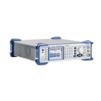
Instrument Design and Function Description R&S SMB
1407.0806.82 3.4 E-6
Automatic Level control
W
ith the means of a directional coupler a small part of the output of the power amplifier is fed to an RF
detector. The output signal of this RF detector is fed to the Automatic Level Control (ALC) unit. The ALC
sets the Level Control Voltage controlling the AM modulators to reach the desired output level.
Step Attenuator and reverse power protection
Due to the limited dynamic range of the ALC RF detector the regulated RF signal is attenuated with
passive attenuators. The step attenuator is a settable attenuator with known attenuation.
At the RF output of the RF Board a reverse power protection circuitry detects RF power fed into the RF
Board from outside the instrument. To protect the SMB100A against damage a relay disconnects the RF
output, when a reverse power of more than approximately 34 dBm is detected. In standby or power off
mode this relay is also in off state to protect the RF output of the instrument from damage.
Supply voltage control and filtering
The module supply voltages are filtered by means of passive filtering and additional active voltage
regulators. Linear regulators with very good noise and distortion suppression characteristics have been
implemented based on operational amplifier circuitry.
Power Supply Module
The power supply module provides all necessary voltages for the operation of the signal generator. It can
be switched on and off by means of the power switch on the rear panel. After switch-on, the instrument is
either in standby or in operating mode, depending on a value stored in an internal EEPROM.
The power supply works over a wide input voltage range from 100 V to 240 V (±10 %) and AC supply
frequencies form 50 Hz to 60 Hz (±5 %).
On the secondary side, the power supply generates three DC voltages (+5.0 V, +13.25 V, -13.25 V) and
one standby voltage (+5 V), all ±5 %.
The secondary voltages are open-circuit-proof and short-circuit-proof with respect to ground and each
other.
The power inlet module contains two fuses. Replace these fuses only with type and rating specified on the
rear panel. If the replaced fuse blows again, change the module.
Further fuses are fitted on the BASIS BOARD as a means of fire protection.
Basis Board
The Basis Board of the signal generator involves the following components and modules:
Fuses
Each supply voltage is fused with one or several fuses on the Basis Board.

 Loading...