Chapter 5 Resets, Interrupts, and General System Control
MC9S08QE128 MCU Series Reference Manual, Rev. 2
Freescale Semiconductor 103
5.8.6 System Device Identification Register (SDIDH, SDIDL)
These high page read-only registers are included so host development systems can identify the HCS08
derivative. This allows the development software to recognize where specific memory blocks, registers,
and control bits are located in a target MCU.
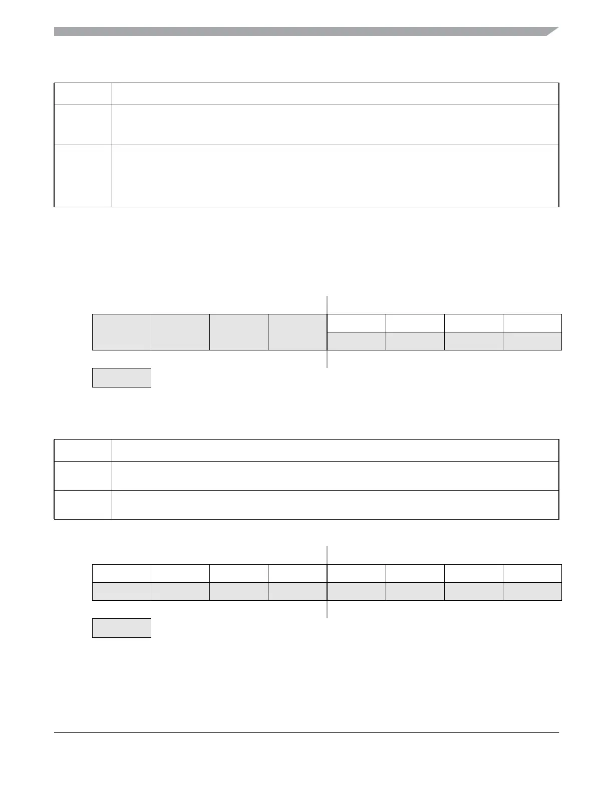
Figure 5-7. System Device Identification Register — High (SDIDH)
1
IIC1PS
IIC1 Pin Select— This bit selects the location of the SDA1 and SCL1 pins of the IIC1 module.
0 SDA1 on PTA2, SCL1 on PTA3.
1 SDA1 on PTB6, SCL1 on PTB7.
0
ACIC1
Analog Comparator 1 to Input Capture Enable— This bit connects the output of ACMP1 to TPM1 input
channel 0. See Chapter 9, “Analog Comparator 3V (ACMPVLPV1),” and Chapter 16, “Timer/Pulse-Width
Modulator (S08TPMV3),” for more details on this feature.
0 ACMP output not connected to TPM1 input channel 0.
1 ACMP output connected to TPM1 input channel 0.
76543210
R ID11 ID10 ID9 ID8
W
Reset: ———— 0000
= Unimplemented or Reserved
Table 5-8. SDIDH Register Field Descriptions
Field Description
7:4
Reserved
Bits 7:4 are reserved. Reading these bits will result in an indeterminate value; writes have no effect.
3:0
ID[11:8]
Part Identification Number — Each derivative in the HCS08 Family has a unique identification number. The
MC9S08QE128 is hard coded to the value 0x015. See also ID bits in Table 5-9.
76543210
R ID7 ID6 ID5 ID4 ID3 ID2 ID1 ID0
W
Reset: 00010101
= Unimplemented or Reserved
Figure 5-8. System Device Identification Register — Low (SDIDL)
Table 5-7. SOPT2 Register Field Descriptions (continued)
Field Description
 Loading...