Chapter 7 Keyboard Interrupt (S08KBIV2)
MC9S08QE128 MCU Series Reference Manual, Rev. 2
142 Freescale Semiconductor
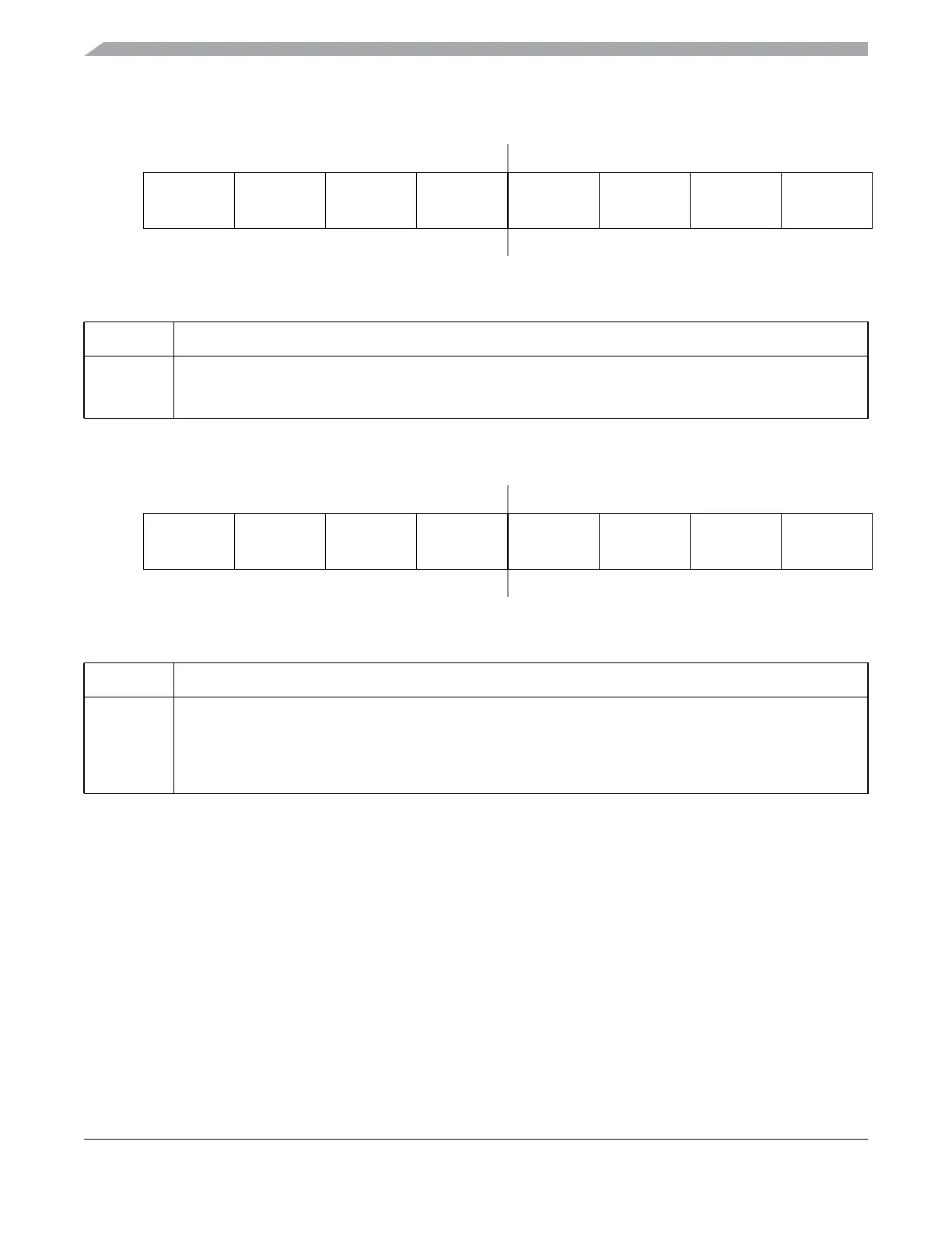
7.3.2 KBI Interrupt Pin Select Register (KBIxPE)
7.3.3 KBI Interrupt Edge Select Register (KBIxES)
7.4 Functional Description
Writing to the KBIPEn bits in the keyboardx interrupt pin enable register (KBIxPE) independently enables
or disables each port pin. Each port can be configured as edge sensitive or edge and level sensitive based
on the KBIMOD bit in the keyboard interrupt status and control register (KBIxSC). Edge sensitivity can
be software programmed to be either falling or rising; the level can be either low or high. The polarity of
the edge or edge and level sensitivity is selected using the KBEDGn bits in the keyboard interrupt edge
select register (KBIxES).
Synchronous logic is used to detect edges. Prior to detecting an edge, enabled port inputs must be at the
deasserted logic level. A falling edge is detected when an enabled port input signal is seen as a logic 1 (the
deasserted level) during one bus cycle and then a logic 0 (the asserted level) during the next cycle. A rising
76543210
R
KBIPE7 KBIPE6 KBIPE5 KBIPE4 KBIPE3 KBIPE2 KBIPE1 KBIPE0
W
Reset: 00000000
Figure 7-3. KBI Interrupt Pin Select Register (KBIxPE)
Table 7-4. KBIxPE Register Field Descriptions
Field Description
7:0
KBIPE[7:0]
KBI Interrupt Pin Selects — Each of the KBIPEn bits enable the corresponding KBI interrupt pin.
0 Pin not enabled as interrupt.
1 Pin enabled as interrupt.
76543210
R
KBEDG7 KBEDG6 KBEDG5 KBEDG4 KBEDG3 KBEDG2 KBEDG1 KBEDG0
W
Reset: 00000000
Figure 7-4. KBI Edge Select Register (KBIxES)
Table 7-5. KBIxES Register Field Descriptions
Field Description
7:0
KBEDG[7:0]
KBI Edge Selects — Each of the KBEDGn bits serves a dual purpose by selecting the polarity of the active
interrupt edge as well as selecting a pull-up or pull-down device if enabled.
0 A pull-up device is connected to the associated pin and detects falling edge/low level for interrupt generation.
1 A pull-down device is connected to the associated pin and detects rising edge/high level for interrupt
generation.