Chapter 7 Keyboard Interrupt (S08KBIV2)
MC9S08QE128 MCU Series Reference Manual, Rev. 2
Freescale Semiconductor 141
7.3 Register Definition
The KBI includes three registers:
• An 8-bit pin status and control register.
• An 8-bit pin enable register.
• An 8-bit edge select register.
Refer to the direct-page register summary in the Memory chapter for the absolute address assignments for
all KBI registers. This section refers to registers and control bits only by their names and relative address
offsets.
Some MCUs may have more than one KBI, so register names include placeholder characters to identify
which KBI is being referenced.
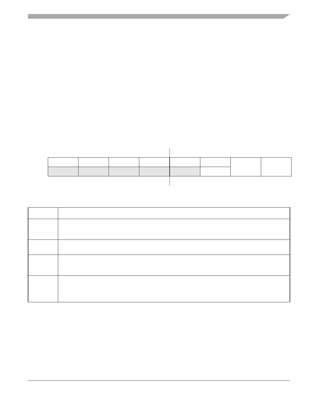
7.3.1 KBI Interrupt Status and Control Register (KBIxSC)
76543210
R0000KBF0
KBIE KBIMOD
W KBACK
Reset: 00000000
Figure 7-2. KBI Interrupt Status and Control Register (KBIxSC)
Table 7-3. KBIxSC Register Field Descriptions
Field Description
3
KBF
KBI Interrupt Flag — KBF indicates when a KBI interrupt is detected. Writes have no effect on KBF.
0 No KBI interrupt detected.
1 KBI interrupt detected.
2
KBACK
KBI Interrupt Acknowledge — Writing a 1 to KBACK is part of the flag clearing mechanism. KBACK always
reads as 0.
1
KBIE
KBI Interrupt Enable — KBIE determines whether a KBI interrupt is requested.
0 KBI interrupt request not enabled.
1 KBI interrupt request enabled.
0
KBIMOD
KBI Detection Mode — KBIMOD (along with the KBIES bits) controls the detection mode of the KBI interrupt
pins.
0 KBI pins detect edges only.
1 KBI pins detect both edges and levels.


 To Next Page